Hydraulic pressure-type cable tunnel cleaning device

A cleaning device, hydraulic technology, applied in the direction of mechanically driven excavators/dredgers, etc., can solve the problems of no soil cleaning device, large mud discharge resistance, long construction time, etc., to ensure smooth discharge and prevent gap leakage , the effect of high utilization rate

Inactive Publication Date: 2016-01-27
DONGYING POWER SUPPLY COMPANY STATE GRID SHANDONG ELECTRIC POWER +2
View PDF4 Cites 3 Cited by
  • Summary
  • Abstract
  • Description
  • Claims
  • Application Information

AI Technical Summary

Problems solved by technology

At present, among trenchless construction equipment, there is another type of drilling device, which uses a flexible shaft or a built-in drive motor to directly drill holes. It is small in size, and the whole device enters the inside of the tunnel when drilling, and can realize non-linear tunnel excavation. , because its power is all concentrated on the drill bit, so after the drilling is completed, the broken soil remains in the hole, and it needs to be injected with water or inserted into the hole to discharge the broken soil. Due to the large amount of broken soil, the resistance to mud discharge is relatively large, and the water consumption It is also relatively large, and the construction time is long. At present, there is no soil cleaning device specially designed for the modified drilling device

Method used


Image

  • Hydraulic pressure-type cable tunnel cleaning device
  • Hydraulic pressure-type cable tunnel cleaning device

Examples


Embodiment Construction

[0022] The present invention will be further described in detail below in conjunction with the accompanying drawings and specific embodiments.

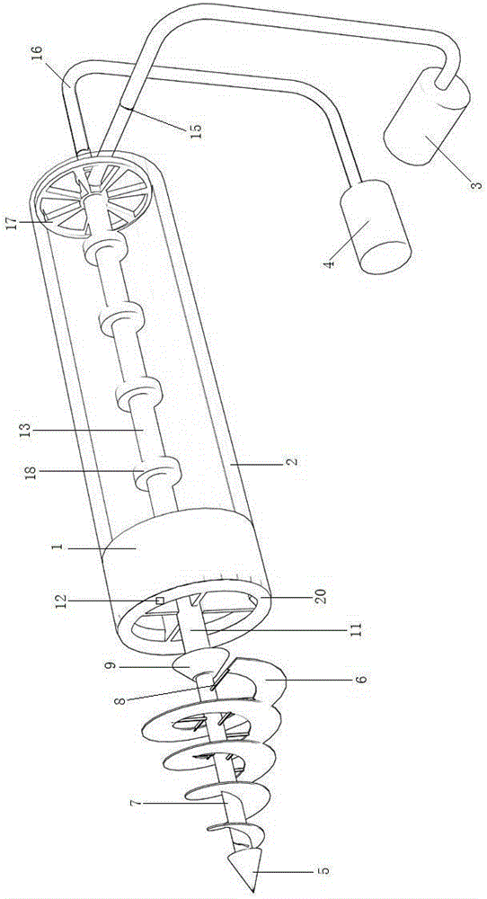
[0023] Such as Figure 1-2 As shown, the hydraulic cable tunnel cleaning device includes a transmission device, a water spray device, a hard flared pipe 1, a soft mud pipe 2, a water pump 3, and a drive motor 4; the transmission device consists of a conical cover 5, a conical spiral Transmission piece 6, transmission shaft 7 constitute; Cone cover 5 is fixed on the left end of transmission shaft 7; The right part runs through the water spray device and cooperates with the water spray device to rotate and seal; the left end of the water spray device is a conical sprinkler cover 9, and a cavity is arranged inside the conical sprinkler cover 9; the bottom surface of the left side of the conical sprinkler cover 9 is in the circumferential direction Evenly have the water spray channel 10 that is connected with the cavity; The center is f...


PUM


Abstract

The invention discloses a hydraulic pressure-type cable tunnel cleaning device, and relates to the technical field of cable casting construction tools. The hydraulic pressure-type cable tunnel cleaning device comprises a conveying device, a water spraying device, a hard flared tube, a soft mud tube, a water pump and a driving motor; the conveying device consists of a conical cover, a conical spiral conveying sheet and a transmission shaft; the conical cover is fixedly arranged on the left end of the transmission shaft; the conical spiral conveying sheet is located behind the conical cover and is fixedly connected with the transmission shaft through support rods; the right part of the transmission shaft penetrates through the water spraying device and is in rotary hermetic match with the water spraying device; the left end of the water spraying device is a truncated cone-shaped water sprinkling cover; a cavity is arranged in the truncated cone-shaped water sprinkling cover; a soft shaft is coaxially arranged in a soft water inlet sleeve pipe; the output end on the left side of the soft shaft is connected with the right end of the transmission shaft; and the right end of the hard flared tube is in butt joint communication with the soft mud tube. The hydraulic pressure-type cable tunnel cleaning device is high in mud cleaning efficiency, small in work resistance and small in water consumption amount and can clean cleanly.

Description

technical field [0001] The invention relates to the technical field of cable laying construction tools. Background technique [0002] The traditional pipeline laying method is to use manual excavation to bury the pipeline underground. Laying pipelines in this way is inefficient and seriously damages surface vegetation. There is also a non-excavation construction machine. The machine is to dig a larger square pit at both ends, put the machine in the pit at one end, first punch a hole with a puncher, and then use it to expand the hole. This laying machine has limited laying distance, complicated construction and low efficiency. [0003] Trenchless technology refers to the construction technology of laying, repairing and replacing underground pipelines and cables without digging trenches on the ground. Because of its advantages such as fast construction speed, little interference to the ground, low overall cost, and good safety, it has been increasingly used in the construct...

Claims


Application Information

Patent Timeline
Patent Type & Authority Applications(China)
IPC IPC(8): E02F3/88
Inventor 周彦强王红霞徐志云李千军霍立成刘东
Owner DONGYING POWER SUPPLY COMPANY STATE GRID SHANDONG ELECTRIC POWER
Why Eureka
Try Eureka