Three-dimensional flow centrifugal blower with low-speed multistage vertical split cylinder structure

A ternary flow and blower technology, which is applied to pump components, mechanical equipment, radial flow pumps, etc., can solve the problems of unsmooth gas flow in corners, poor mechanical performance stability, and reduce the overall efficiency of the fan, so as to improve the efficiency of the fan. High efficiency, enhanced sealing effect, simple and reasonable structure

Active Publication Date: 2016-01-27
SHANGHAI HUAGU BLOWER CO LTD
View PDF8 Cites 7 Cited by
  • Summary
  • Abstract
  • Description
  • Claims
  • Application Information

AI Technical Summary

Problems solved by technology

Compared with the casting mechanism, its disadvantages are: due to the limitation of the welding structure, the gas flow in the curved part is not smooth, and the flow loss increases during the turning process, which reduces the overall efficiency of the fan; at the same time, its mechanical properties are stable compared with the casting structure In addition, because the shell of this product adopts a horizontal split structure, the shell is not suitable for interchangeability, the utilization rate is low, and it is easy to cause waste

Method used


Image

  • Three-dimensional flow centrifugal blower with low-speed multistage vertical split cylinder structure
  • Three-dimensional flow centrifugal blower with low-speed multistage vertical split cylinder structure
  • Three-dimensional flow centrifugal blower with low-speed multistage vertical split cylinder structure

Examples


Embodiment Construction

[0024] The present invention will be further described below in conjunction with the accompanying drawings and embodiments.

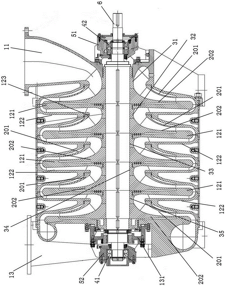
[0025] see figure 1 As shown, a three-dimensional flow centrifugal blower with a low-speed multi-stage vertical split cylindrical structure of the present invention is composed of a stator 1, a rotor 2, a bearing 4, a shaft seat 5 and a main shaft 6. The rotor 2 is located in the stator 1, and the two ends of the rotor 2 are respectively fixed by bearings 41, 42, and the two bearings 41, 42 are located in the bearing housings 51, 52.

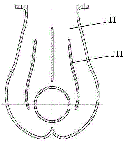
[0026] In the embodiment of the present invention, the rotor 2 is composed of five stages of independent impellers. The impeller (see figure 2 ), it adopts a closed three-dimensional flow structure, and the blades are three-dimensional streamlined. Based on computational fluid dynamics (CFD) technology, the flow channel of the gas in the blade is optimized to ensure the smooth flow of gas in the impeller. The aerodyna...


PUM


Abstract

The invention relates to a three-dimensional flow centrifugal blower with a low-speed multistage vertical split cylinder structure. The three-dimensional flow centrifugal blower consists of a rotor, a stator and bearings, wherein the stator comprises a three-dimensional flow impeller, a main shaft, a sealing axle sleeve and balance discs; the stator comprises an inlet chamber, an exhaust chamber, separation discs and bearing seats; each separation disc consists of a cover disc and an impeller disc; fixing elements such as a vaneless diffuser, a curve and a backflow device are formed between the separation discs; the rotor is fixed in the stator by a thrust bearing and a support bearing mounted in the bearing seats; and the three-dimensional flow impeller comprises a first stage impeller, a middle stage impeller and a last stage impeller. The flow pass part of the blower is subjected to optimal design based on a CFD technology; a closed type integrated casting structure is adopted by the three-dimensional flow impeller; labyrinth seal structures are added on the end faces of shaft discs of the impellers; flow guide ring structures are added on the impeller inlet ends; flow guide rings and the cover discs are subjected to integrated casting; and labyrinth seal structures are added on the end faces of the balance discs. The three-dimensional flow centrifugal blower with a low-speed multistage vertical split cylinder structure has the characteristics of low cost, high efficiency, stable mechanical property and the like, and is a blower with high cost performance.

Description

technical field [0001] The invention relates to a low-speed multi-stage cylindrical structure blower. The low-speed multi-stage cylindrical structure centrifugal blower of the present invention is especially suitable for environmental protection fields such as desulfurization and oxidation process sections of power plants and aeration in sewage treatment plants. Background technique [0002] In the prior art, blowers mainly include the following types: Roots blowers, binary flow multistage centrifugal blowers, and single-stage high-speed blowers. Roots blowers are relatively cheap, but they have high energy consumption, high noise, many easily damaged and consumable parts, and frequent maintenance are their main disadvantages; binary flow multi-stage centrifugal blowers are moderately priced, but relatively low in efficiency; single-stage high-speed Although the blower has high efficiency, its price is high and the maintenance cost is high. If a gearbox is used for speeding ...

Claims


Application Information

Patent Timeline
Patent Type & Authority Applications(China)
IPC IPC(8): F04D17/08F04D29/28F04D29/44F04D29/08
Inventor 宋国文陈泽谷
Owner SHANGHAI HUAGU BLOWER CO LTD
Why Eureka
Try Eureka