Tubular heating furnace with efficient and uniform heating
A tubular heating furnace and uniform heating technology, which is applied in the direction of water heaters, fluid heaters, lighting and heating equipment, etc., can solve the problems of uneven heating of the medium, and achieve the effect of improving heating efficiency and heating uniformity
- Summary
- Abstract
- Description
- Claims
- Application Information
AI Technical Summary
Problems solved by technology
Method used
Image

Examples
Embodiment 1
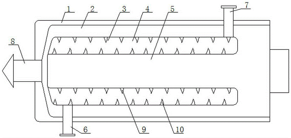
[0028] The high-efficiency uniform heating tubular heating furnace of the present invention comprises a tubular furnace body, the tubular furnace body is provided with a combustion chamber and a heat exchange chamber, one end of the tubular furnace body is the combustion chamber inlet communicating with the combustion chamber, The other end of the tubular furnace body is a smoke exhaust port that communicates with the combustion chamber. A heating medium outlet is provided on the tubular furnace body near the combustion chamber entrance, and a heating medium inlet is provided on the tubular furnace body near the smoke exhaust port. The heat exchange chamber communicates with the heated medium inlet and the heated medium outlet; the combustion chamber includes an outer combustion chamber and an inner combustion chamber, and the outer combustion chamber is sleeved on the inner wall of the tubular furnace body. The bottoms of the inner combustion chamber and the outer combustion c...
Embodiment 2
[0030]The high-efficiency uniform heating tubular heating furnace of the present invention comprises a tubular furnace body, the tubular furnace body is provided with a combustion chamber and a heat exchange chamber, one end of the tubular furnace body is the combustion chamber inlet communicating with the combustion chamber, The other end of the tubular furnace body is a smoke exhaust port that communicates with the combustion chamber. A heating medium outlet is provided on the tubular furnace body near the combustion chamber entrance, and a heating medium inlet is provided on the tubular furnace body near the smoke exhaust port. The heat exchange chamber communicates with the heated medium inlet and the heated medium outlet; the combustion chamber includes an outer combustion chamber and an inner combustion chamber, and the outer combustion chamber is sleeved on the inner wall of the tubular furnace body. The bottoms of the inner combustion chamber and the outer combustion ch...
Embodiment 3
[0032] On the basis of Embodiment 1 or Embodiment 2, the heating medium inlet is arranged tangentially on the tube furnace body.
PUM
 Abstract
Description
Claims
Application Information
 - Generate Ideas
- Intellectual Property
- Life Sciences
- Materials
- Tech Scout
- Unparalleled Data Quality
- Higher Quality Content
- 60% Fewer Hallucinations
Browse by: Latest US Patents, China's latest patents, Technical Efficacy Thesaurus, Application Domain, Technology Topic, Popular Technical Reports.
© 2025 PatSnap. All rights reserved.Legal|Privacy policy|Modern Slavery Act Transparency Statement|Sitemap|About US| Contact US: help@patsnap.com