Transformer iron core demagnetization method

A transformer core and transformer technology, applied in the field of transformer residual magnetism, can solve the problems of long demagnetization time, demagnetization failure, hysteresis loop offset, etc., and achieve the effect of short demagnetization time

Active Publication Date: 2016-01-27
XI AN JIAOTONG UNIV +1
View PDF5 Cites 5 Cited by
  • Summary
  • Abstract
  • Description
  • Claims
  • Application Information

AI Technical Summary

Problems solved by technology
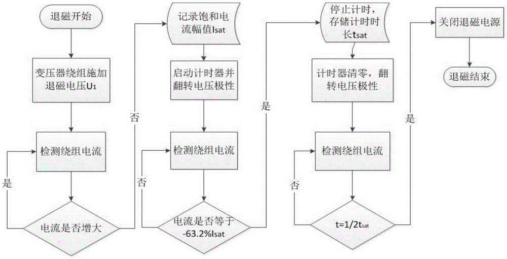
However, this method takes a long time to demagnetize, and it is easy to cause the hysteresis loop to shift during the process of changing the

Method used


Image

  • Transformer iron core demagnetization method
  • Transformer iron core demagnetization method
  • Transformer iron core demagnetization method

Examples


Embodiment

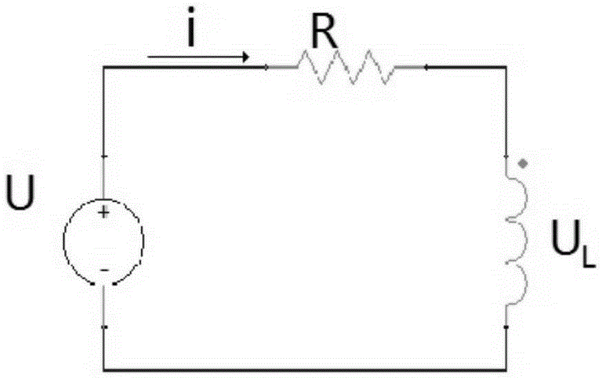
[0040] Take a single-phase transformer demagnetization as an example, build as Figure 4 The simulation model shown in the figure: U represents the DC power supply, R represents the DC resistance of the transformer, n represents the transformation ratio of the transformer, L 1 Indicates the transformer leakage inductance, L 2 Indicates the equivalent excitation inductance of the transformer, P indicates the high-voltage side of the transformer, and S indicates the low-voltage side of the transformer; the rated capacity of the transformer is 403MVA, the rated voltage is 199.18kV / 162.64kV, the rated magnetic flux of the high-voltage side is 634V*s, and the DC resistance of the transformer is 0.08Ω , demagnetize from the high-voltage side of the transformer, the demagnetization DC voltage amplitude is 8V, and the initial residual magnetism is -500V*s, and the demagnetization is carried out according to the method of the present invention. Figure 5 is the demagnetization DC volt...


PUM


Abstract

The invention discloses a transformer iron core demagnetization method and especially provides a method for demagnetizing the iron core of a transformer after the DC resistance test. According to the invention, the voltage is applied onto the primary winding of a transformer by a DC power supply for three times, wherein the voltage-applying amplitude is the same each time and the polarity thereof is alternately changed. The voltage-applying duration is determined based on the acquired current waveform of the primary side of the transformer. During the first two times, the current applied onto the primary winding of the transformer reaches a forward peak value and a reverse peak value respectively. During the third time, the current applied onto the primary winding of the transformer occupies only half of the duration from the forward peak value to 63.2% of the reverse peak value. Through the above three voltage application processes, the iron core of the transformer is demagnetized. Based on the above method, the demagnetization duration is greatly shortened and the demagnetization effect is ensured at the same time. Meanwhile, the demagnetization equipment is small in power and good in practicality.

Description

technical field [0001] The invention belongs to the technical field of transformer residual magnetism, and in particular relates to a transformer iron core demagnetization method. Background technique [0002] According to the requirements of the "Preventive Test Regulations for Electric Power Equipment", large transformers must be tested for DC resistance after maintenance or after 1 to 3 years of operation. The magnetic field generated by the DC current will leave a large amount of residual magnetism in the transformer core. When the transformer is switched on without load, affected by the residual magnetism of the iron core and the closing phase angle of the circuit breaker, the iron core may be saturated, resulting in a large inrush current of the transformer on the side of the sudden voltage change, resulting in a malfunction of the differential protection Tripping, causing the transformer to fail repeatedly in operation; a large value of the excitation inrush current w...

Claims


Application Information

Patent Timeline
IPC IPC(8): H01F13/00
Inventor 郝治国谭婷月张保会张晓静刘志远于晓军邹洪森韦鹏尹磊
Owner XI AN JIAOTONG UNIV
Why Eureka
Try Eureka