
Photon polarization state compensation method based on complete reconstruction

A technology of photon polarization and complete reconstruction, applied in photon quantum communication and key distribution, it can solve problems such as restricting compensation accuracy, vulnerability to attacks, and reducing compensation timeliness, so as to eliminate adverse effects and improve timeliness and accuracy. Effect

Inactive Publication Date: 2016-01-27
PLA UNIV OF SCI & TECH
View PDF5 Cites 4 Cited by
  • Summary
  • Abstract
  • Description
  • Claims
  • Application Information

AI Technical Summary

Problems solved by technology

Polarization self-compensation scheme based on bidirectional optical path structure Since photons go back and forth through the optical fiber twice, the transmission distance is limited, the system efficiency is relatively low, and it is vulnerable to attack
Interrupted polarization compensation is easy to implement, but it is inefficient, using about 10% of the time for polarization compensation
Although the time division multiplexing polarization compensation scheme and the wavelength division multiplexing polarization compensation scheme can achieve accurate compensation for signal light by compensating the reference light, the system needs to pay a large cost in multiplexing the reference light
Therefore, these polarization compensation methods cannot balance efficiency, distance and cost
Patent 201510228202.6 proposes a photon polarization state compensation method based on joint feedback of bit error rate and uncertainty rate. Although this method makes up for the above defects, it takes extra time to observe the results of trial compensation during the compensation process. , so it will inevitably reduce the timeliness of compensation, and then restrict the accuracy of compensation

Method used


Image

  • Photon polarization state compensation method based on complete reconstruction

Examples


Embodiment Construction

[0034] The present invention will be further described below in conjunction with the accompanying drawings and embodiments.

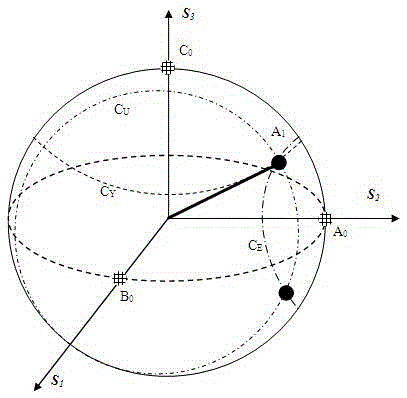
[0035] Such as figure 1 As shown, the sending end and the receiving end randomly use three sets of non-orthogonal polarization bases to encode and decode the photon polarization state, and the sending end and the receiving end use the same probability for each set of bases.

[0036] The polarization state of the photons expected to be received by the quantum key distribution system is represented by a point on the Poincaré sphere, the angle between the real-time polarization state and the expected polarization state corresponds to the current bit error rate, and the real-time polarization state and the other two non-orthogonal basis The included angle corresponds to the current two uncertainty rates;

[0037] Count the bit error rate of the photon polarization state to its own polarization state at the sending end and the receiving end, and position th...


PUM


Abstract

The invention provides a photon polarization state compensation method based on complete reconstruction. A transmitting end and a receiving end encode and decode the photon polarization state by randomly using three groups of non-orthogonal polarization bases; the photon polarization state to be received in expectation is expressed by a point on the poincare sphere; the error rate of the photon polarization state to the polarization state itself is calculated when the bases are matched, the uncertainty rate of the photon polarization state to one of the groups of non-orthogonal bases is calculated when the bases are not matched, the uncertainty rate of the photon polarization state to the other one of the groups of non-orthogonal bases is further calculated when the bases are not matched, so that the complete reconstruction of the photon polarization state is realized, a polarization control apparatus is adjusted, and the photon polarization state compensation of a quantum key distribution system is realized. According to the invention, without influencing the communication efficiency and distance of the quantum key distribution system and increasing the system cost, the bad influence of trail compensation is eliminated by complete reconstruction, and the timeliness and the accuracy of real-time compensation to the two non-orthogonal photon polarization states are further improved.

Description

technical field [0001] The invention relates to a photon polarization state compensation technology, in particular to a quantum key distribution system using polarization encoding, in particular to a photon polarization state compensation method based on complete reconstruction. Background technique [0002] At present, the polarization compensation schemes used in the known quantum key distribution system mainly include two-way optical path polarization self-compensation, interruption compensation, time division multiplexing compensation and wavelength division multiplexing compensation [Several polarization compensation technologies of optical fiber quantum key distribution system, Wang Jian, Advances in Lasers and Optoelectronics]. In the polarization self-compensation scheme based on the bidirectional optical path structure, the transmission distance is limited because the photons go back and forth through the optical fiber twice, the system efficiency is relatively low,...

Claims


Application Information

Patent Timeline
IPC IPC(8): H04L9/08H04B10/70
Inventor 周华朱勇苏洋徐智勇赵继勇吴传信何敏王艺敏沈荟萍王衍波
Owner PLA UNIV OF SCI & TECH
Learn More