High-power equipment remote monitoring analysis system

A remote monitoring and analysis system technology, applied in the field of remote monitoring, can solve the problems of large instantaneous current of high-power equipment, single monitoring method, and large power consumption, so as to ensure stability and reliability, high efficiency of the detection system, and save construction costs Effect

Inactive Publication Date: 2016-01-27
UNIV OF ELECTRONICS SCI & TECH OF CHINA ZHONGSHAN INST
View PDF5 Cites 2 Cited by
  • Summary
  • Abstract
  • Description
  • Claims
  • Application Information

AI Technical Summary

Problems solved by technology

[0002] With the rapid development of industry, high-power equipment is more and more widely used in industrial production, equipment manufacturing, material processing, agriculture, biopharmaceutical and other fields, and the requirements for safe operation of high-power equipment are getting higher and higher. Start and stop, large power consumption, low production capacity, low production efficiency, very large instantaneous current when high-power equipment starts, resulting in serious loss of drive motors and high-power equipment, short service life, and low operating efficiency. Most large-scale equipment is usually unattended when it is running, and the operating status of the equipment cannot be understood in real time, and equipment failures cannot be detected and dealt with in a timely manner
[0003] At present, the existing monitoring equipment adopts wired transmission mode, and each channel of video needs to have its own independent transmission line, and the network utilization rate is low; and the monitoring system needs to be built with a special line, and the cost is relatively high; during work, monitoring personnel need to be constantly Staring at the monitoring screen to check, the workload is heavy; the monitoring method is single, and it is impossible to truly understand the operating status of the equipment, and to achieve timely prevention and treatment

Method used


Image

  • High-power equipment remote monitoring analysis system
  • High-power equipment remote monitoring analysis system
  • High-power equipment remote monitoring analysis system

Examples


Embodiment Construction

[0027] In order to make the object, technical solution and advantages of the present invention clearer, the present invention will be further described in detail below in combination with specific embodiments and with reference to the accompanying drawings. It should be understood that these descriptions are exemplary only, and are not intended to limit the scope of the present invention. Also, in the following description, descriptions of well-known structures and techniques are omitted to avoid unnecessarily obscuring the concept of the present invention.

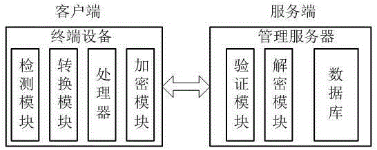
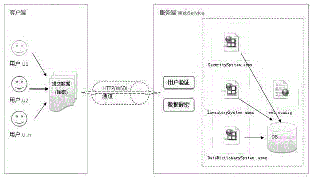
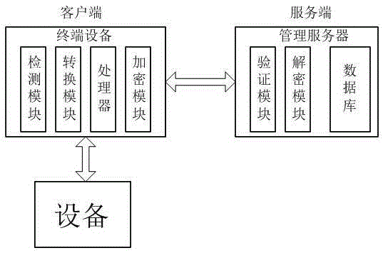
[0028] Such as figure 1 and figure 2 As shown, a high-power equipment remote monitoring and analysis system, the system is set in the C / S network architecture of the client and the server, the network architecture includes the server and the client, and the server is a management server , the management server has a built-in database, a verification module and a decryption module, and the management server includes a d...


PUM


Abstract

The invention particularly relates to a high-power equipment remote monitoring analysis system. The system is arranged in a C / S network architecture of a client and a service end. The network architecture comprises the service end and the client. The service end is a management server which is internally provided with a database, a verification module and a decryption module. The client is a terminal device which comprises a detection module, a conversion module, a processor and an encryption module. The service end and the client adopt web or WDSL communication connection therebetween. The encryption module is used for encrypting data submitted by the client and sending the encrypted data to the service end. The verification module is used for performing user verification of received data and receiving user data after verification is successful. The decryption module is used for decrypting the received user data and processing the user data after decryption. The invention provides a detection system which can simply and effectively detect equipment and reduce the cost of remote detection.

Description

technical field [0001] The invention relates to the technical field of remote monitoring, in particular to a remote monitoring and analysis system for high-power equipment. technical background [0002] With the rapid development of industry, high-power equipment is more and more widely used in industrial production, equipment manufacturing, material processing, agriculture, biopharmaceutical and other fields, and the requirements for safe operation of high-power equipment are getting higher and higher. Start and stop, large power consumption, low production capacity, low production efficiency, very large instantaneous current when high-power equipment starts, resulting in serious loss of drive motors and high-power equipment, short service life, and low operating efficiency. Most large-scale equipment is usually unattended when it is running, and the operating status of the equipment cannot be understood in real time, and equipment failures cannot be detected and dealt with...

Claims


Application Information

Patent Timeline
IPC IPC(8): H04L29/08H04L29/06
CPCH04L63/0428H04L67/025H04L67/01
Inventor 石世光宋喜佳夏百战
Owner UNIV OF ELECTRONICS SCI & TECH OF CHINA ZHONGSHAN INST
Why Eureka
Try Eureka