Near-space airborne-to-ground real-time imaging system

A real-time imaging system and imaging system technology, applied in the field of ground real-time imaging systems, can solve the problems of reduced sensitivity, high cost, and increased cost, and achieve the effects of strong pertinence, high accuracy and strong timeliness

Inactive Publication Date: 2016-01-27
OCEANOGRAPHIC INSTR RES INST SHANDONG ACAD OF SCI
View PDF5 Cites 16 Cited by
  • Summary
  • Abstract
  • Description
  • Claims
  • Application Information

AI Technical Summary

Problems solved by technology

However, increasing the focal length of the camera will increase the volume of the imaging system, and the processing difficulty of optical parts will also increase, and the cost will increase; and as the flying height of the vehicle decreases, the coverage of the ground will also decrease; Using a detector with a small pixel size can give full play to the imaging potential of the optical system, but the current technological level has made the pixel size reach its minimum value. As the detector pixel size decreases, the shot noise will also decrease. Increase, the minimum illuminance received by the pixel decreases, and the sensitivity decreases
In addition, these methods all need to upgrade the main hardware system, and the cost is relatively high.

Method used


Image

  • Near-space airborne-to-ground real-time imaging system
  • Near-space airborne-to-ground real-time imaging system
  • Near-space airborne-to-ground real-time imaging system

Examples


Embodiment 1

[0027] Example 1: Optical window

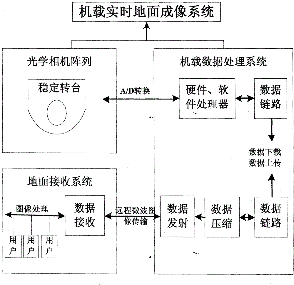
[0028] Airborne ground real-time imaging system consists of figure 1 As shown, it includes: optical camera array, airborne data processing system and image transmission equipment for real-time transmission, the hood is installed on the shell of the imaging system, and the hood is installed on the top of the hood with an openable and closed function.

[0029] Composed of quartz glass windows (optical windows), in order to adjust the attitude of the camera array in real time and avoid the influence of aircraft platform flip, pitch, roll, etc. on camera imaging, the optical camera and quartz glass windows are installed on a closed mechanical turntable.

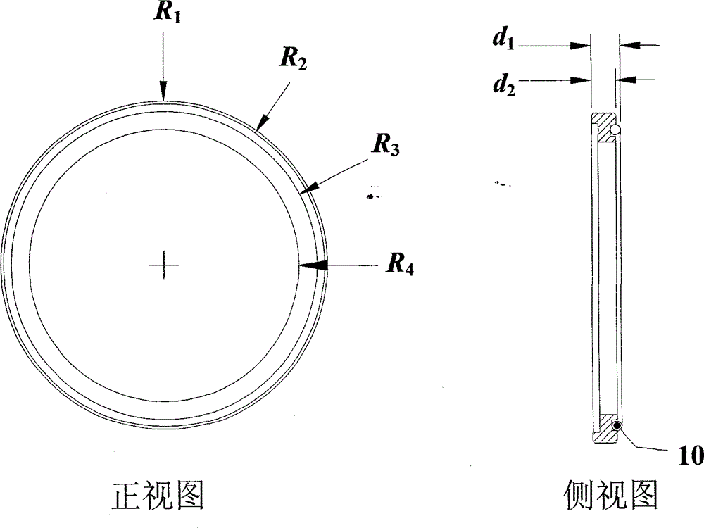
[0030]The optical window provides the optical signal entrance for the imaging system and meets the requirements of the field of view. When the system is imaging, the imaging light enters the optical system through the optical window and is imaged on the CCD imaging focal plane. Since the optica...

Embodiment 2

[0037] Example 2: Optical Camera Array

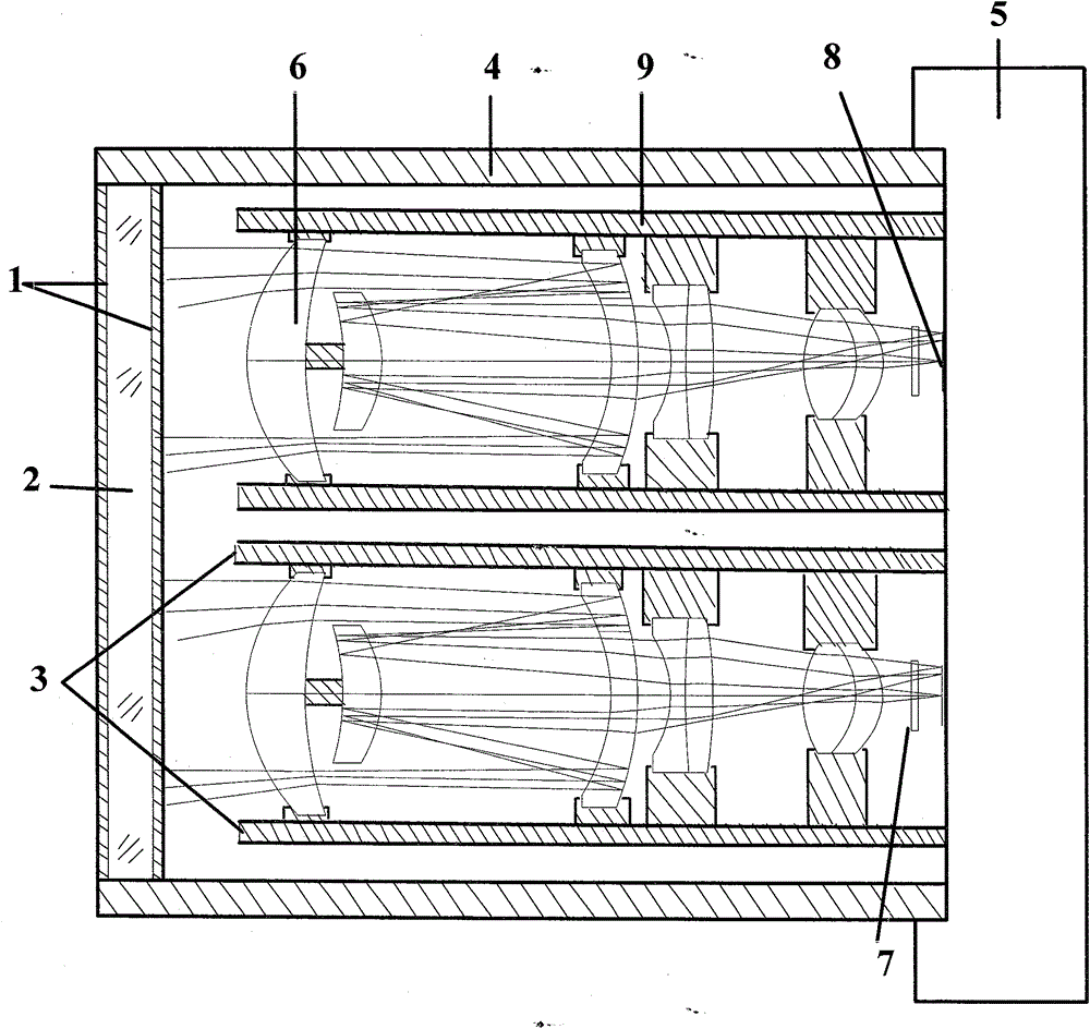
[0038] The optical camera array consists of four identical optical cameras. Specifically, the structure of the optical camera array is as follows figure 2 shown.

[0039] Since the payload is carried on the UAV aircraft in the near space, the distance from the ground is relatively long. In order to clearly obtain the geographical information of the ground target, a larger focal length and a larger clear aperture are required. The longer the focal length of the system, according to the imaging principle, the larger the image of the target on the detector after passing through the optical system, the easier it is to identify. But the volume of the system is directly proportional to the size of the focal length, the longer the focal length, the larger the volume of the system. For this reason, the structural form of the optical lens in the optical camera of the patent of the present invention adopts a catadioptric structure, and its str...

Embodiment 3

[0078] Embodiment 3: Image acquisition and acquisition

[0079] The target light enters the camera through the optical window (2), focuses the target on the linear array CCD detector (8), and converts the optical signal into an electrical signal; then converts it into a digital signal through an analog / digital converter (A / D) ;Then the signal is compressed by the microprocessor (MPU) and converted into a specific image file format and stored on the memory card, and transmitted to the airborne data processing system through the output interface, and the target signal is solidified to a camera motherboard. Large-scale integrated circuit chips collect and process the charge information accumulated by the CCD during the imaging process, and compress, display and store the obtained scene images. The camera adopts an advanced data acquisition and processing system, which can improve the overall operation response speed and computing power of the imaging system, and can process a lar...


PUM


Abstract

The invention discloses a high resolution imaging system. The system comprises an optical camera, an airborne data processing system and image transmission equipment of real-time transmission. A shell top of the imaging system is provided with a light shield mask. The optical camera is formed by four lens arrays. Each lens adopts a linear array CCD. The airborne data processing system carries out splicing processing on an image obtained by each camera so as to acquire a high resolution image with a large field of view scope. Therefore, under the condition that a total number of detection pixels of a focal plane array detector is not increased, the resolution of the imaging system is improved and a detection blind area of the detector, which is brought by a filling factor, is eliminated. The image transmission equipment transmits the image to a ground receiving system in real time so as to process and transmit to a user so that real-time monitoring of a ground target is realized.

Description

technical field [0001] The present invention relates to a real-time imaging system on the ground, especially a high-resolution imaging system, which is mounted on an unmanned aerial vehicle in the adjacent space, and the system includes an optical camera array, an airborne data processing system and an image transmission system for real-time transmission equipment. An expandable and closable shading cover is installed on the top of the housing of the imaging system, and the shading cover moves with the sun to block the stray light of the sun. The optical camera array is composed of four lenses, each lens adopts a linear array CCD, and the four linear array CCD detectors are respectively staggered by half a pixel. In this way, four images of different spatial positions are obtained, and the airborne data processing system stitches the images obtained by each camera to obtain high-resolution images with a large field of view, so that the total number of pixels detected by the f...

Claims


Application Information

Patent Timeline
Patent Type & Authority Applications(China)
IPC IPC(8): H04N7/18G03B11/04
Inventor 孙小玲解维浩周斌刘恩晓李辉
Owner OCEANOGRAPHIC INSTR RES INST SHANDONG ACAD OF SCI
Why Eureka
Try Eureka