Flying object operating system

A technology for operating systems and aircraft, applied in the field of aircraft, can solve problems such as increased energy consumption, reduced operating efficiency of airships, and inability to operate aircraft for a long time, to achieve the effect of ensuring stability

Inactive Publication Date: 2016-01-27
章秀宁
View PDF7 Cites 1 Cited by
  • Summary
  • Abstract
  • Description
  • Claims
  • Application Information

AI Technical Summary

Problems solved by technology

[0016] However, as in the prior art, when the position of the aircraft is controlled by using a power plant, the energy consumption for driving the above-mentioned airship increases, thereby not only reducing the operating efficiency of the airship, but also making it impossible to operate the aircraft for a long time.

Method used


Image

  • Flying object operating system
  • Flying object operating system
  • Flying object operating system

Examples


Embodiment Construction

[0089] Hereinafter, specific embodiments of the above-mentioned aircraft operating system based on the present invention will be described in detail with reference to the accompanying drawings.

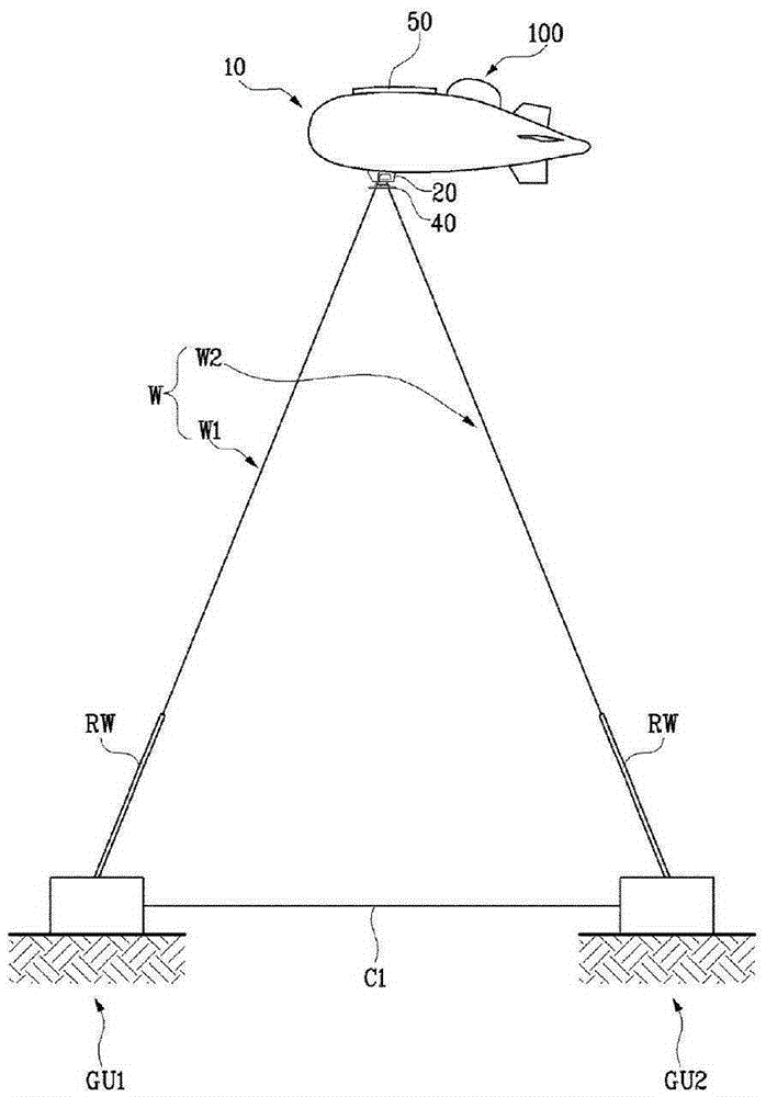
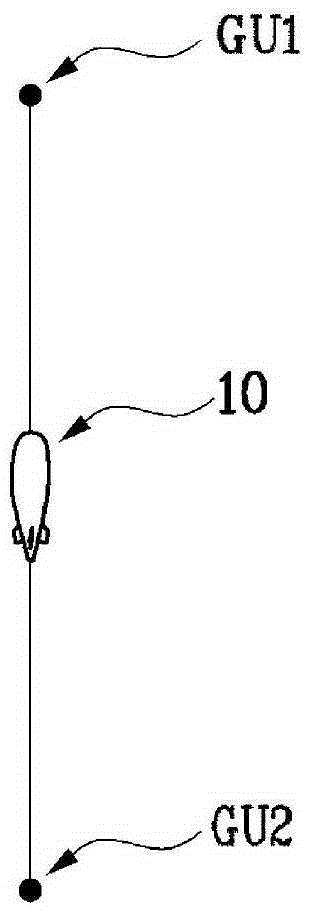
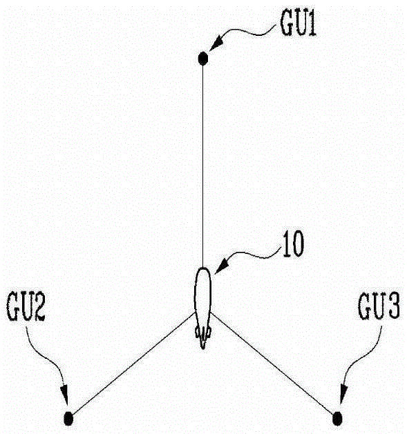
[0090] figure 1 In order to briefly show the structure diagram based on the preferred embodiment of the aircraft operating system of the present invention, Figure 2a to Figure 2c It is an illustration diagram showing the structural form of the field unit constituting the embodiment of the present invention, image 3 is a structural diagram showing a state in which the buoyancy generating unit constituting an embodiment of the present invention is deployed, Figure 4 It is a structural diagram showing a state where the angles of the buoyancy generating unit constituting the embodiment of the present invention are deformed.

[0091] Accordingly, the aircraft operating system based on the present invention generally includes the aircraft 10 , the field units GU1 , GU2 and the wire uni...


PUM


Abstract

The present invention relates to a system for operating a flying object that is flown from the ground. The flying object operation system includes a flying object that is filled with a gas therein to stay in the sky, a ground unit installed on the ground, a wire unit connecting the flying object to the ground unit, and a buoyancy-generation unit disposed on a side of the flying object to obtain buoyancy through friction with air, thereby transferring the obtained buoyancy to the flying object. In the present invention, since additional wind-derived buoyancy obtained by the buoyancy-generation unit connected to the flying object is further generated, sufficient buoyancy may be supplied to the flying object in a high-altitude environment to stably operate the flying object. Also, since power generated by using the wind power generation unit is transmitted to the ground through the wire unit, the flying object operation system may be utilized as wind power generation equipment.

Description

technical field [0001] The present invention relates to an aircraft, and more specifically, relates to an aircraft operating system that is connected to the ground to receive power from the ground and adjusts the aircraft to stay at a predetermined position. Background technique [0002] In general, aircraft, as objects flying in the air, can be roughly classified into self-powered aircraft such as airplanes and unpowered aircraft such as airships and gliders. [0003] An airship, which is a representative example of an unpowered aircraft, is an aircraft in which gas lighter than air is injected into airbags to obtain most of the lift force from the gas. [0004] However, aircraft having propulsion by installing an auxiliary power device such as an engine on an unpowered aircraft have been widely used recently. [0005] Since the airship as described above can maintain a balanced state even without any power, the airship is more stable, less noisy and has a lower fuel consu...

Claims


Application Information

Patent Timeline
Patent Type & Authority Applications(China)
IPC IPC(8): B64B1/44B64B1/52
CPCB64B1/52B64F1/14F03D5/00F05B2240/922Y02E10/70B64B1/12B64D39/00B64F3/02Y02T50/80B64U10/60B64B1/44B64C39/022G01C21/005
Inventor 章秀宁
Owner 章秀宁
Why Eureka
Try Eureka