Position detection device

A detection device and detection surface technology, applied in the direction of instrument, electrical digital data processing, data processing input/output process, etc., can solve problems such as difficulty in determining which point the finger is placed on, differential input detection not being practical, etc. Achieve the effect of fast sampling speed, high elimination effect, and elimination of external noise

Active Publication Date: 2016-01-27
WACOM CO LTD
View PDF11 Cites 5 Cited by
  • Summary
  • Abstract
  • Description
  • Claims
  • Application Information

AI Technical Summary

Problems solved by technology

[0006] However, in a multi-touch panel that detects multiple fingers at the same time, the detection based on the differential input has not been put into practical use.
The reason for this is that, in differential input, it is necessary to be able to detect the approach of a finger at multiple points, so it is difficult to determine at which point the finger is placed even if a signal is detected.

Method used


Image

  • Position detection device
  • Position detection device
  • Position detection device

Examples


no. 1 example

[0055] [First Example (First Embodiment)]

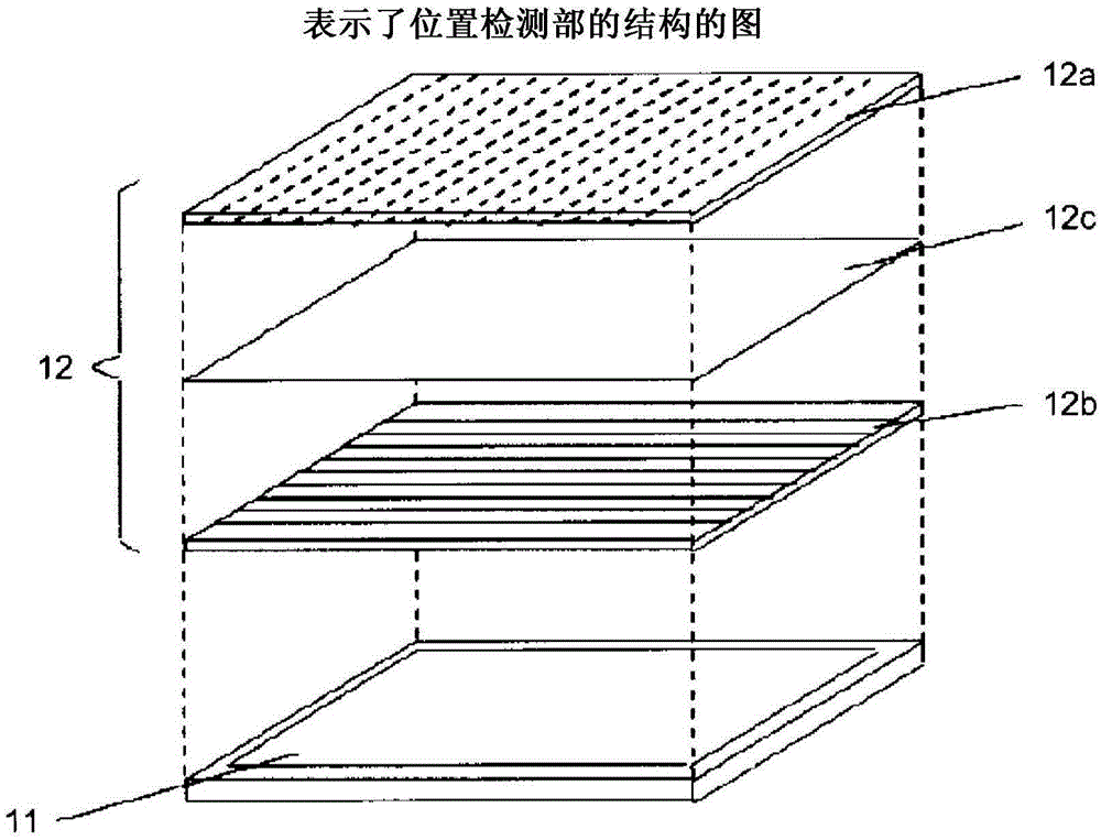
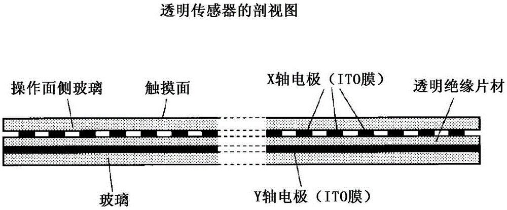
[0056] figure 1 It is a figure which shows the structure of the position detection part of the 1st Example of the position detection apparatus of this invention. In the drawing, 11 is an LCD panel, and 12 is a transparent sensor having electrodes formed of ITO (Indium Tin Oxide). 12a is an ITO glass formed by arranging a plurality of ITO electrode lines along the X direction. 12b is an ITO glass formed by arranging a plurality of ITO electrode lines along the Y direction. 12c is a PET (polyethylene terephthalate) film with uniform thickness. The transparent sensor 12 is manufactured by making the ITO glass 12a and the ITO glass 12b face each other, and bonding the PET film 12c between them. The transparent sensor 12 is arranged to overlap the LCD panel 11 such that the detection area just overlaps the display area of ​​the LCD panel 11 . In addition, the X electrodes on the ITO glass 12a and the Y electrodes on the ITO glass 12...

no. 2 example

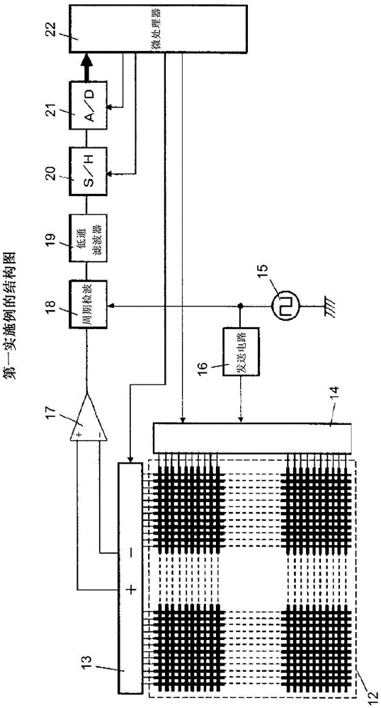
[0079] Figure 13 It is a figure which shows the structure of the 2nd Example of the position detection apparatus of this invention. In this embodiment, a configuration is shown in which a plurality of circuits for processing received signals from the receiving electrodes are provided, and these circuits are operated simultaneously to increase the sampling speed as a whole.

[0080] In this embodiment, the position detection unit also becomes figure 1 as well as figure 2 same construction. exist Figure 13 Among them, 23 is a transparent sensor, 67 electrodes (X1-X67) are arranged along the X direction, and 30 electrodes (Y1-Y30) are arranged along the Y direction. 24 is an analog multiplexer connected to the Y electrodes of the transparent sensor 23 to select one electrode from the Y electrodes.

[0081] 25 is a transmission signal generation circuit that generates a signal of a predetermined frequency, and an output signal thereof is supplied to a transmission circuit...


PUM


Abstract

This invention provides a multi-touch touchscreen (position detection device) that is resistant to noise and allows stable input at multiple points via multiple fingers. A transmission signal outputted by a transmission-signal generation circuit is supplied to prescribed electrodes among a plurality of electrodes laid out in a first direction of a position detection sensor. A number of adjacent electrodes are selected from among a plurality of electrodes laid out in a second direction that is perpendicular to the aforementioned first direction of the position detection sensor, the number of electrodes selected being even and greater than or equal to four. Half of the selected electrodes, the electrodes constituting said half being adjacent to each other, with those on the ends excluded, are connected to a first input terminal of a differential-amplifier circuit. The remaining half is connected to a second input terminal of said differential-amplifier circuit. The polarity of a signal that appears at the output of a synchronous-detection circuit that synchronously detects the output of the differential-amplifier circuit is used to determine whether a pointing body placed on the position detection sensor is above an electrode connected to the first input terminal of the differential-amplifier circuit or an electrode connected to the second input terminal of the differential-amplifier circuit.

Description

technical field [0001] The present invention relates to a position detection device for electrostatically detecting a plurality of pointing positions of conductors such as fingers, and more specifically, to detecting the pointing positions of a plurality of pointing bodies on a position detection sensor and reducing noise mixed into the position detection sensor technology to improve detection accuracy. Background technique [0002] In recent years, tablet-type information terminals equipped with touch panels have been widely used. In particular, multi-touch techniques for inputting positions of a plurality of fingers at the same time are gradually being reformed. [0003] As such a technique, for example, as disclosed in Patent Document 1 (JP-A-08-179871), an electrostatic induction method in which a plurality of electrodes are arranged vertically and horizontally on the panel surface and these electrodes are sequentially selected is widely used. The signal strength is ob...

Claims


Application Information

Patent Timeline
Patent Type & Authority Applications(China)
IPC IPC(8): G06F3/041G06F3/044
CPCG06F2203/04104G06F3/0446G06F3/04182G06F3/04166G06F3/0445G06F3/0412G06F3/047
Inventor 桂平勇次
Owner WACOM CO LTD
Why Eureka
Try Eureka