
Whole-course operation system and method for SCR denitration device of coal-fired power plant boiler

A technology of coal-fired power plants and DCS systems, applied in separation methods, chemical instruments and methods, and dispersed particle separation, etc., can solve problems such as excessive nitrogen oxide emissions, SCR denitrification devices cannot be put into operation, and boilers in coal-fired power plants cannot be solved. , to achieve the effect of realizing the whole process of operation

Pending Publication Date: 2016-02-03
任治民 +2
View PDF0 Cites 4 Cited by
  • Summary
  • Abstract
  • Description
  • Claims
  • Application Information

AI Technical Summary

Problems solved by technology

However, when the load of the unit is below 50%, the flue gas temperature at the inlet of the SCR denitrification device is lower than 300°C, especially during the start-up and shutdown of the boiler, the temperature of the flue gas at the inlet of the SCR denitrification device is much lower than 300°C, resulting in the failure of the SCR denitrification device to operate. Transport, excessive nitrogen oxide emissions
At present, the known technical measures such as graded economizer and economizer bypass flue can shorten the time of not putting the SCR denitrification device into operation after the unit is started and before shutting down, but it cannot solve the problem of putting the SCR denitrification device into operation in the whole process of coal-fired power plant boilers. technical issues

Method used


Image

  • Whole-course operation system and method for SCR denitration device of coal-fired power plant boiler
  • Whole-course operation system and method for SCR denitration device of coal-fired power plant boiler

Examples

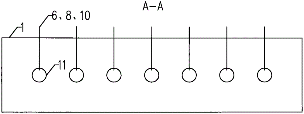

Embodiment Construction

[0025] Below in conjunction with accompanying drawing, the present invention will be further described with specific embodiment, see Figure 1-2 .

[0026] Such as figure 1 As shown, on the denitrification inlet flue 1, the expansion joints 2 of the denitrification inlet flue, multiple sets of flue gas heater systems arranged in parallel, heat insulation guards 12, flow guide baffles 17, and ammonia injection pipes are arranged in sequence along the flue gas flow direction. 19.

[0027] Such as figure 2 As shown, the number of the above-mentioned multiple sets of flue gas heater systems is determined according to the physical heat and heat balance formula. In this embodiment, the number of flue gas heater systems arranged in the denitrification inlet flue 1 is 7 sets.

[0028] The above-mentioned flue gas heater system includes: flue gas temperature measuring point 3 at the denitrification inlet, flue gas heater compressed air pipe 4, flue gas heater oil gun compressed air...


PUM


Abstract

The invention discloses a whole-course operation system and method for an SCR denitration device of a coal-fired power plant boiler, and belongs to the field of environmental protection equipment. According to the whole-course operation system, a denitration inlet flue expansion joint, multiple flue gas heater systems arranged in parallel, a heat insulation protective plate, a flow guide baffle and an ammonia spraying pipeline are sequentially arranged on a denitration inlet flue in the flue gas flow direction. After the coal-fired power plant boiler is ignited to start up, when a DCS system shows that the flue gas temperature of a denitration inlet and the flue gas temperature before the ammonia spraying pipeline are lower than lower limit of catalyst allowed ammonia spraying temperature, the DCS system automatically controls the flue gas heater systems to start up according to a set program. When the flue gas temperature before the ammonia spraying pipeline is higher than the lower limit of catalyst allowed ammonia spraying temperature by 10 DEG C or more, the DCS system automatically turns off the corresponding flue gas heater systems. Finally, the flue gas temperature before the ammonia spraying pipeline is kept above the lower limit of catalyst allowed ammonia spraying temperature.

Description

technical field [0001] The invention relates to a system and a method for full operation of an SCR denitrification device in a coal-fired power plant boiler, in particular to the normal operation of the SCR denitrification device during the start-up and shutdown of the boiler in a coal-fired power plant, and belongs to the field of environmental protection equipment. Background technique [0002] The lower limit of peak regulation for thermal power plants required by power grid scheduling is 50% of the rated load. Coal-fired power plants that use selective catalytic reduction (SCR) denitrification have achieved unit loads of more than 50% through combustion adjustment or necessary technical transformation. When the flue gas temperature at the inlet of the SCR denitrification device reaches above 300°C, the SCR denitrification device can be put into operation normally. However, when the load of the unit is below 50%, the flue gas temperature at the inlet of the SCR denitrific...

Claims


Application Information

Patent Timeline
IPC IPC(8): B01D53/86B01D53/78B01D53/56F23J15/08
Inventor 任治民白德龙张劲松李永富解冠宇
Owner 任治民
Learn More