Micro-gas ignition combustion-supporting combustion device

A combustion device, ignition and combustion-supporting technology, which is applied in the direction of burning with various fuels, burning with block fuels and gaseous fuels, burning with liquid fuels and gaseous fuels, etc., and can solve the problem of short life of the cathode and easy burning of the burner nozzle No damage, pollution denitrification catalyst, desulfurization slurry and other problems, to achieve the effect of strengthening heat and mass exchange process, fast flame propagation speed, and reducing fuel cost

Pending Publication Date: 2021-01-22
XIAN TPRI BOILER ENVIRONMENTAL PROTECTION ENG CO LTD +1
View PDF0 Cites 5 Cited by
  • Summary
  • Abstract
  • Description
  • Claims
  • Application Information

AI Technical Summary

Problems solved by technology

[0003] Using less oil guns for ignition and combustion support, the fuel consumption for starting and stopping ignition and combustion support of a single unit remains high, and the fuel cost of the power plant is too high
In addition, there are problems such as unburned oil polluting the denitrification catalyst and desulfurization slurry during the boiler start-up process, which leads to the failure of normal operation of the environmental protection equipment and brings great pressure on the environmental protection operation indicators of the power plant.
Using a micro-oil ignition burner for ignition and combustion, the fuel cost is greatly reduced, but there are problems such as burner nozzles are easy to burn out, coking and clogging, and it is impossible to directly input anthracite during the cold start-up stage, and the burnout rate of pulverized coal is poor at the initial stage of combustion
Limited by its ignition energy, the plasma ignition burner has poor adaptability to coal types, and cannot be used to ignite low-volatile coal types such as anthracite and low-quality lean coal.
And its system is complex, the cathode life is short, and the daily operation and maintenance workload is heavy

Method used


Image

  • Micro-gas ignition combustion-supporting combustion device
  • Micro-gas ignition combustion-supporting combustion device
  • Micro-gas ignition combustion-supporting combustion device

Examples


Embodiment Construction

[0027] The present invention is described in further detail below in conjunction with accompanying drawing:

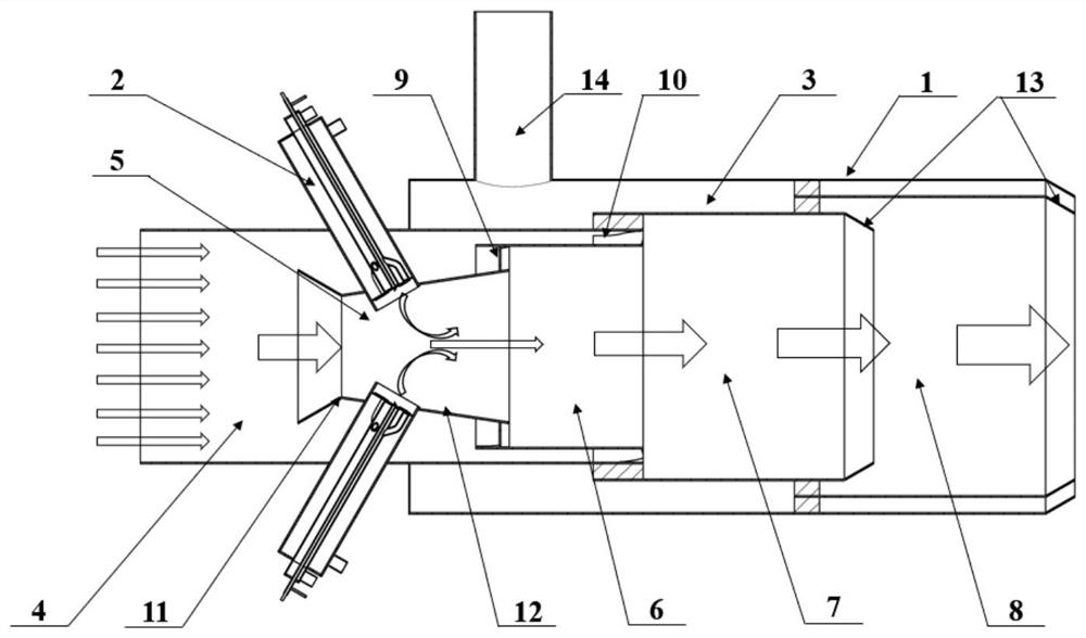
[0028] refer to figure 1 , figure 2 and image 3 , the micro-gas ignition and combustion-supporting combustion device of the present invention includes a pulverized coal combustion device 1, a film cooling wind device 3 and several natural gas combustion devices 2; the pulverized coal combustion device 1 includes a primary air powder pipe 4, a pulverized coal secondary combustion chamber 7. Pulverized coal tertiary combustion chamber 8, pulverized coal pre-combustion chamber 5, pulverized coal primary combustion chamber 6; pulverized coal pre-combustion chamber 5 is a structure that shrinks first and then expands, and pulverized coal pre-combustion chamber 5 includes a first hollow circular platform 11 And the second hollow round table 12, the bottom of the first hollow round table 11 is facing the incoming flow direction of the primary wind powder pipe 4, the top o...


PUM


Abstract

The invention discloses a micro-gas ignition combustion-supporting combustion device. The device comprises a pulverized coal combustion device, a gas film cooling air device, and a plurality of natural gas combustion devices. The pulverized coal combustion device comprises a primary air pulverized coal pipe, a pulverized coal secondary combustion chamber, a pulverized coal tertiary combustion chamber, a pulverized coal pre-combustion chamber, and a pulverized coal primary combustion chamber. Each of the natural gas combustion devices comprises a rotational flow disc, a combustor shell, a branch gas pipe, a main gas pipe, a gas inlet, a gas air distribution plate, an ignition device, and a combustion-supporting air inlet. The micro-gas ignition combustion-supporting combustion device can achieve whole-process commissioning of environment-friendly equipment in the starting, stopping and combustion-supporting process of a boiler, and the fuel cost is greatly reduced.

Description

technical field [0001] The invention belongs to the technical field of start-up and ignition of coal-fired power plant boilers, and relates to a micro-gas ignition and combustion-supporting combustion device. Background technique [0002] Under the current power market conditions, the operating hours of boilers in power plants have dropped significantly compared to before, and the flexible operation of units requires frequent start-stops and long-term low-load operation, which puts forward new requirements for ignition and combustion of power plant boilers. At present, the mainstream coal-fired boiler ignition and combustion-supporting technologies can be divided into fuel-saving ignition technology and oil-free ignition technology. Fuel-saving ignition technology mainly includes low-oil ignition and micro-oil ignition technology, and oil-free ignition technology mainly refers to plasma ignition technology. [0003] Using less oil guns for ignition and combustion, the fuel c...

Claims


Application Information

Patent Timeline
Patent Type & Authority Applications(China)
IPC IPC(8): F23C5/08F23D1/02F23Q9/00
CPCF23C5/08F23D1/02F23Q9/00
Inventor 李文锋王玖斌陈飞云姬海民曾多周飞唐荣富申冀康
Owner XIAN TPRI BOILER ENVIRONMENTAL PROTECTION ENG CO LTD
Why Eureka
Try Eureka