Smoke jet device

A technology of jet flow device and smoke exhaust pipe, applied in the direction of exhaust device, muffler device, jet pump, etc., can solve the problem of not long product service life, affecting the jet flow effect, etc., so as to reduce friction, improve the jet flow effect, and improve smoke The effect of gas handling capacity

Active Publication Date: 2017-11-21
中国船舶集团有限公司第七一一研究所
View PDF7 Cites 0 Cited by
  • Summary
  • Abstract
  • Description
  • Claims
  • Application Information

AI Technical Summary

Problems solved by technology

[0011] However, because the jet technology has only been applied in the field of diesel engine exhaust treatment in recent years, the exhaust jet devices on the market still have defects such as easy formation of vortex in the exhaust jet device, affecting the jet effect, and insufficient service life of the product.

Method used


Image

  • Smoke jet device
  • Smoke jet device
  • Smoke jet device

Examples


Embodiment Construction

[0040] The application will be further described in detail below in conjunction with the accompanying drawings and embodiments. It should be understood that the specific embodiments described here are only used to explain related inventions, rather than to limit the invention. It should also be noted that, for ease of description, only parts related to the invention are shown in the drawings.

[0041] It should be noted that, in the case of no conflict, the embodiments in the present application and the features in the embodiments can be combined with each other. The present application will be described in detail below with reference to the accompanying drawings and embodiments.

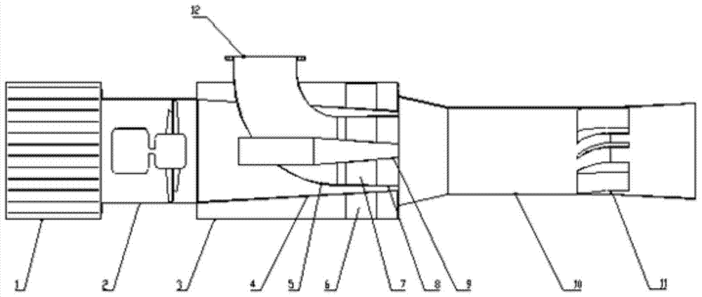
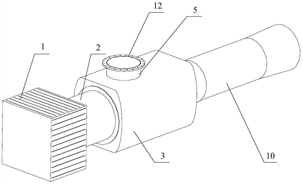
[0042] figure 1 It is a schematic structural diagram of a smoke exhaust jet device provided by an embodiment of the present invention. figure 2 It is a schematic diagram of the appearance of the smoke exhaust jet device.

[0043] Such as figure 1 and figure 2 As shown, in this embodiment, th...


PUM


Abstract

The invention discloses a smoke exhaust jet device, which comprises a fan, a housing, an outer nozzle, a smoke exhaust pipe, a central nozzle and a mixing pipe; the fan is fixed on the first side of the housing; the outer nozzle is fixed in the housing , the large-diameter end is fixed in the first side, communicated with the fan to form a jet air flow channel, the small-diameter end is fixed in the second side of the housing, and communicates with the mixing pipe; one end of the exhaust pipe extends out of the housing, and the other end Extending into the outer nozzle, fixed in the second side, forming an air flow channel with the outer nozzle, and communicating with the mixing pipe; the central nozzle is fixed in the smoke exhaust pipe, and one end extends out of the smoke exhaust pipe to communicate with the jet air flow channel, and the other One end communicates with the mixing tube; the first end of the mixing tube is fixed on the second side, and the port diameter of the first end is larger than the diameter of the small-diameter end of the outer nozzle. The invention realizes the multi-flow channel design, provides excellent aerodynamic characteristics, reduces the vortex formed inside, realizes better jet flow effect, and improves the service life.

Description

technical field [0001] The invention relates to the technical field of smoke emission control application, in particular to a smoke exhaust jet device. Background technique [0002] Offshore platform is a comprehensive offshore engineering equipment for offshore oil drilling, storage, transportation and personnel living. It is a working base for subsea oil and gas exploration and exploitation. [0003] According to the structural characteristics and working status, it can be divided into fixed and mobile platforms. The semi-submersible offshore platform has gradually developed into the world's mainstream mobile platform in deep-sea oil extraction due to its strong anti-wind and wave capability, excellent motion performance, huge deck area and loading capacity, and high operating efficiency. The diesel generator set is the "heart" to ensure the normal operation of the offshore platform, providing power supply for each drilling equipment on the offshore platform and emergency...

Claims


Application Information

Patent Timeline
Patent Type & Authority Patents(China)
IPC IPC(8): F01N3/05F04F5/16
Inventor 刘晓良刘建成方水旺崔世明朱晓健肖英龙
Owner 中国船舶集团有限公司第七一一研究所
Why Eureka
Try Eureka