
Base crane and fan assembly thereof

A component and fan technology, which is applied in the field of floor crane and its fan components, can solve the problems of poor air flow, abnormal sound, loud noise, etc., and achieve the effect of improving heat exchange efficiency, preventing abnormal sound and reducing noise

Active Publication Date: 2016-02-03
TCL AIR CONDITIONER ZHONGSHAN CO LTD
View PDF7 Cites 4 Cited by
  • Summary
  • Abstract
  • Description
  • Claims
  • Application Information

AI Technical Summary

Problems solved by technology

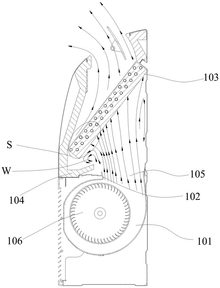
Due to the limitation of the internal space of the crane, the evaporator 103 and the plane where the vent 105 are located are arranged at an angle, rather than in parallel, resulting in uneven distribution of the flow field of the strong exhaust air path, and the flow field density close to the volute tongue 102 bigger
And because the space between the evaporator part S near the volute tongue 102 and the centrifugal volute 101 is small, the wind resistance is very large, resulting in poor air flow and obvious vortex W
Finally, the heat transfer efficiency of the part S of the evaporator 103 close to the volute tongue 102 is very low, the overall heat transfer efficiency of the evaporator 103 is reduced, and the noise is large, resulting in abnormal noise

Method used


Image

  • Base crane and fan assembly thereof
  • Base crane and fan assembly thereof
  • Base crane and fan assembly thereof

Examples


Embodiment Construction

[0022] It should be understood that the specific embodiments described here are only used to explain the present invention, not to limit the present invention.

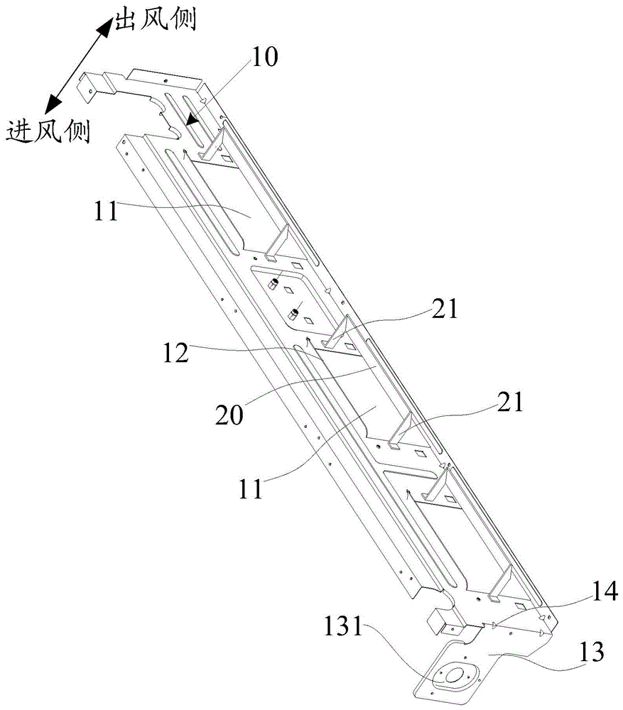
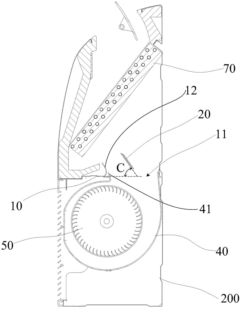
[0023] Such as Figure 2 to Figure 5 as shown, figure 2 is the first structural schematic diagram of a preferred embodiment of the fan assembly of the present invention, image 3 It is a schematic cross-sectional view of a mounted crane installed with a fan assembly according to a preferred embodiment of the present invention, Figure 4 yes image 3 The schematic diagram of the wind flow direction when the crane is working is shown (the direction of the arrow is the direction of the wind flow), Figure 5 It is a second structural schematic diagram of a preferred embodiment of the fan assembly of the present invention.

[0024] refer to Figure 2 to Figure 4 , the fan assembly of the seat crane mentioned in this embodiment includes a middle partition 10 with a motor mounting position (unlabeled), and the middle p...


PUM

PropertyMeasurementUnit
Acute angleaaaaaaaaaa

Abstract

The invention discloses a base crane and a fan assembly thereof. The fan assembly comprises a center spacer with a motor mounting position. A ventilation opening in butt joint with a volute air port of a centrifugal volute is formed in the center spacer. The fan assembly is characterized in that the fan assembly further comprises at least one air guide plate corresponding to the ventilation opening; the length direction of the air guide plates is parallel to that of the center spacer; an acute included angle is formed by the air guide plates and the center spacer; and an opening of the acute included angle faces a volute tongue of the centrifugal volute. According to the base crane and the fan assembly thereof, after air blown out of the volute air port of the centrifugal volute is blown to the air guide plates, the air is guided by the air guide plates to be blown to an evaporator near the volute tongue of the centrifugal volute, the air is made to flow through the evaporator more evenly, and the overall heat exchange efficiency of the evaporator is increased; and vortex generated by turbulence of an air path flow field is weakened, noise is lowered, and abnormal noise is avoided.

Description

technical field [0001] The invention relates to the technical field of air conditioning, in particular to a seat crane and a fan assembly thereof. Background technique [0002] At present, there are two types of wind path structures for floor cranes: suction and strong exhaust. Because the air suction method sucks cold air with low temperature, the mounted crane adopting the air suction method is prone to produce condensed water near the cavity of the wind wheel volute, and the production process is difficult to control. Therefore, the strong air exhaust method is the air path structure commonly used in floor cranes. [0003] Such as figure 1 Shown is a schematic diagram of the structure of the strong exhaust type mounted crane. The centrifugal volute 101 is installed on the middle partition 104, and the middle partition 104 is provided with a vent 105 connected with the volute tuyere, and the centrifugal fan 106 in the centrifugal volute 101 sucks in air from the outside...

Claims


Application Information

Patent Timeline
IPC IPC(8): F24F13/08F04D29/46F04D25/08F24F13/24
Inventor 潘志升陈国豪贾鹏黄志方张琪宇余静
Owner TCL AIR CONDITIONER ZHONGSHAN CO LTD
Learn More