Current detection circuit of fuel oil injection solenoid valve

A current detection circuit and fuel injection technology, applied in the direction of measuring current/voltage, measuring device, measuring electrical variables, etc., can solve the problems of high cost and large installation volume, and achieve the effect of low price, small size and wide application range

Inactive Publication Date: 2016-02-03
镇江恒驰科技有限公司
View PDF5 Cites 1 Cited by
  • Summary
  • Abstract
  • Description
  • Claims
  • Application Information

AI Technical Summary

Problems solved by technology

[0004] The current collection method usually used is a current sensor, which has the problems of high cost and large installation volume

Method used


Image

  • Current detection circuit of fuel oil injection solenoid valve
  • Current detection circuit of fuel oil injection solenoid valve
  • Current detection circuit of fuel oil injection solenoid valve

Examples


Embodiment Construction

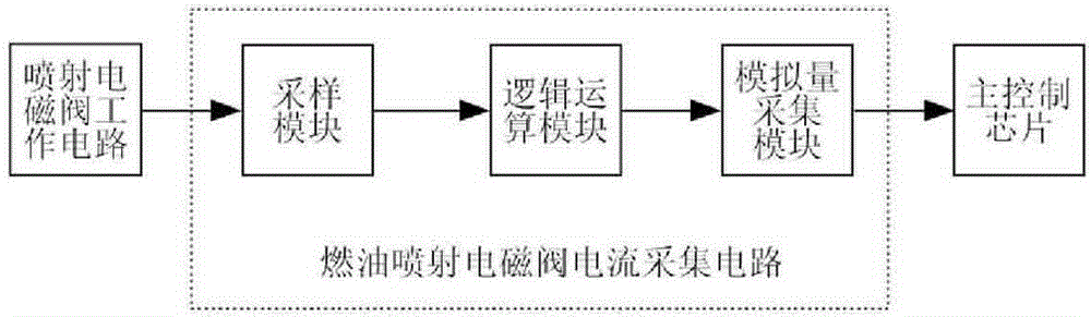
[0016] The specific circuit is attached figure 2 , 3 , 4 shown.

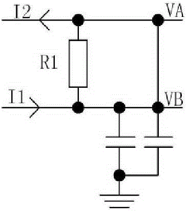
[0017] Sampling module of the present invention such as figure 2 , the circuit is mainly composed of sampling resistor R1, filter capacitors C1, C2 and their connections. The sampling resistor R1 is connected in series to the working circuit of the injection valve, the signal I1 is connected to the low drive output terminal, the signal I2 is connected to GND, and the capacitor One end of C1 is connected to the lower end of R1, and the other end is connected to GND; one end of capacitor C2 is connected to the upper end of R1, and the other end is connected to GND.

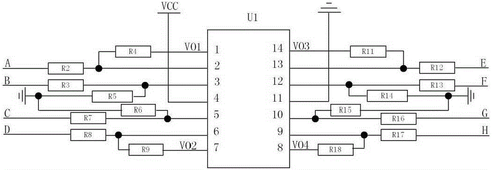
[0018] Logic operation module of the present invention such as image 3 , the circuit is mainly composed of an operational amplifier numbered U1, a resistor and its connection, where R4 is connected between the first pin and the second pin of U1, and R2 is connected between the signal A and the second pin of U1 Between, R3 is connected to signal...


PUM


Abstract

The invention provides a current detection circuit of a fuel oil injection solenoid valve. The current detection circuit is composed of a sampling module, a logic operation module and an analog quantity collection module, wherein the analog quantity collection module is composed of a current-limiting resistor, a filtering capacitor and a voltage stabilizing diode. A work current of the injection solenoid valve flows through the sampling module, a current signal is converted into a small-voltage signal, and after high-frequency interference filtering is carried out, the small-voltage signal is output to the logic operation module, the small-voltage signal is amplified and converted into a digital value which is stabilized in a safety range and subjected to interference filtering, and then the digital value is output to a main control unit. According to the invention, a multichannel operational amplifier chip is utilized, current detection of a plurality of injection solenoid valves can be carried out at the same time, a current sensor in a conventional design is omitted, the application range is wide, the cost is low, and the installation is more convenient.

Description

technical field [0001] The invention relates to the field of automotive electronics, in particular to the current detection of a fuel injection solenoid valve in an engine electronic control system. Background technique [0002] In order to meet the increasingly stringent emission restrictions and further improve the fuel economy, power and operational reliability of the engine, the use of electronic control technology has become a major direction for the development of contemporary diesel engines. The core part of the electronically controlled diesel engine is the electronically controlled fuel injection system. In the time-controlled electronically controlled diesel engine electronically controlled fuel injection system and the pressure time-controlled common rail diesel injection system, fuel injection is usually realized by solenoid valves. Especially in the time-controlled electronically controlled diesel engine injection system, the injection timing and injection volu...

Claims


Application Information

Patent Timeline
Patent Type & Authority Applications(China)
IPC IPC(8): G01R19/00
Inventor 张育华陈浩薛小莉
Owner 镇江恒驰科技有限公司
Why Eureka
Try Eureka