Optical cable branch line protection structure

A technology for protecting structures and optical cables, applied in fiber mechanical structures, optics, light guides, etc., can solve problems such as difficult to achieve fixed length, affect optical fiber signal transmission effect, poor consistency of branch sub-cable lengths, etc., to ensure length consistency, ensure The effect of optical performance and signal transmission effect

Active Publication Date: 2018-09-25
SHENZHEN ACE ARMORED CABLE CO
View PDF6 Cites 2 Cited by
  • Summary
  • Abstract
  • Description
  • Claims
  • Application Information

AI Technical Summary

Problems solved by technology

This branching structure has the following disadvantages: 1. When the optical cable is in use, it is necessary to ensure that the optical fiber has sufficient length so that the optical fiber can move freely, thereby ensuring the optical performance of optical fiber transmission.
However, in the existing structure, encapsulation by potting glue at the branch line of the main cable and the sub-cable will cause the optical fiber in the optical cable at the glue potting position to be fixed, and the optical performance of the fiber cannot be guaranteed, which will affect the signal transmission effect of the fiber; 2. The tensile element of the single-core optical cable in the structure is arranged in the cladding layer of the sub-cable. Since the tensile element can be shaken, it is difficult to achieve a fixed length for the outer cladding layer. When making a branch line, the single-core The length of the sub-cable is uncontrollable, which will lead to poor consistency of the length of the branch sub-cable

Method used


Image

  • Optical cable branch line protection structure
  • Optical cable branch line protection structure
  • Optical cable branch line protection structure

Examples


Embodiment Construction

[0021] In order to illustrate the idea and purpose of the present invention, the present invention will be further described below in conjunction with the accompanying drawings and specific embodiments.

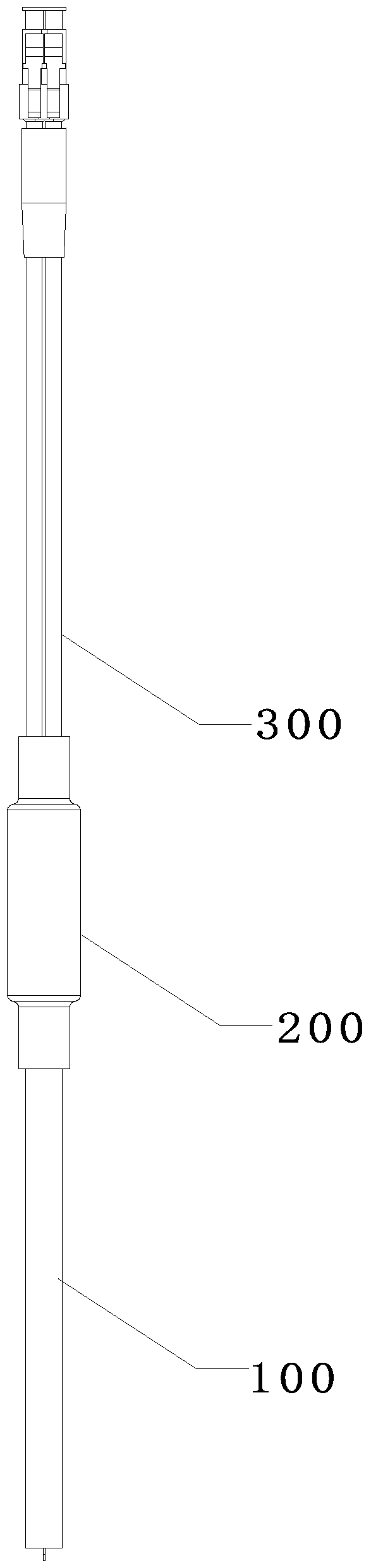
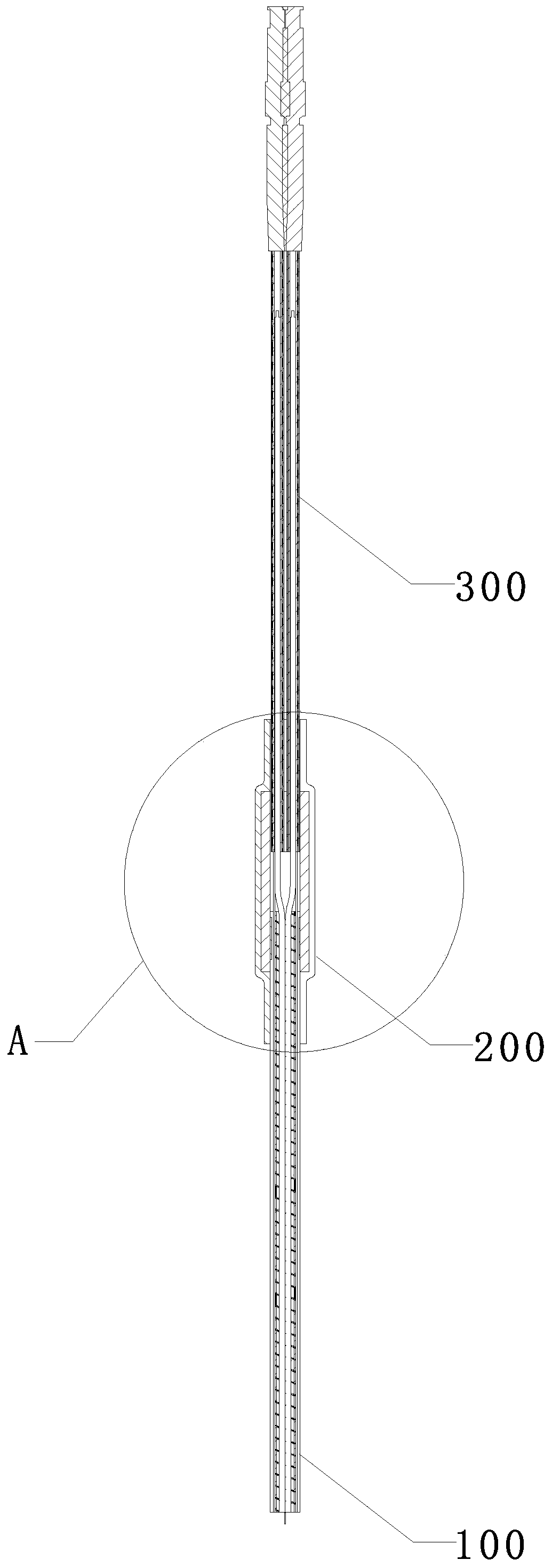
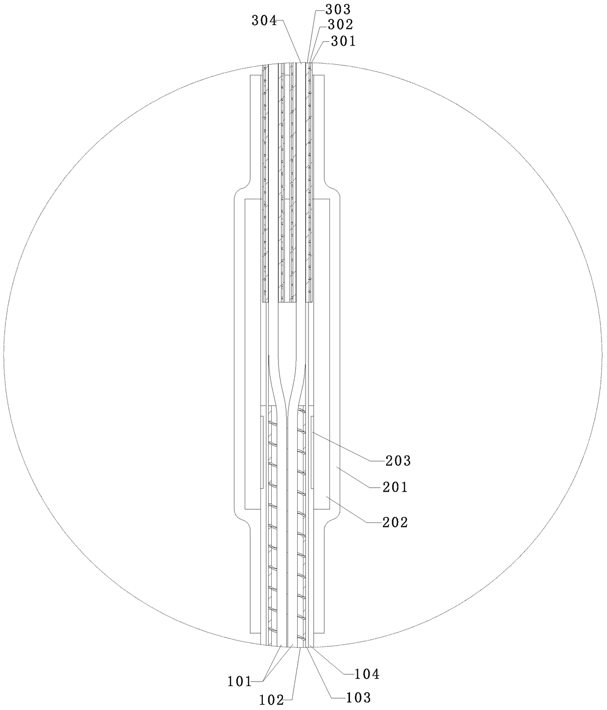
[0022] See figure 1 , figure 2 as shown, figure 1 It is a three-dimensional schematic diagram of the optical cable branching protection structure of the present invention; figure 2 for figure 1 cutaway view. This embodiment discloses an optical cable branching protection structure, which is mainly used for the problem of inconsistency in the lengths of the branch sub-cables caused by the movement of the tension-resisting elements in the optical cable when the optical cable is in the process of branching, as well as the separation between the main cable and the sub-cables. Glue encapsulation at the branch line will cause the optical fiber in the optical cable at the glue filling position to be fixed, which cannot guarantee the optical performance of the optical fiber and...


PUM


Abstract

The present invention discloses an optical cable branching protection structure. The optical cable branching protection structure comprises: a main optical cable, a plurality of sub-optical cables formed by branching the main optical cable, and a deconcentrator sleeved at the outside of the branching of the main optical cable and a plurality of sub-optical cables. A junk ring bush compressing a coating layer sleeves the outside of the main optical cable section, and the sub-optical cable sections have no a junk ring bush. Aramid fibers are located between the coating layer and the steel pipe, and the movement of the aramid fibers may be effectively utilized to make optical fibers in the main optical cable have enough free activity space, so that the optical fibers have enough length to satisfy various usage environment and the optical performance and signal transmission effect of the optical fibers are ensured. According to the invention, single core fibers and aramid fibers are located in the steel pipe, the steel pipe and the coating layer are integrated into one body to fix with a thermoplastic pipe, and the length of the outer coating layer may be determined; and when a branching is made, length of each single core sub-optical fiber is controllable, and the length consistency of the branch sub-optical fiber may be effectively ensured.

Description

Technical field: [0001] The invention relates to the technical field of optical cable communication connection, in particular to an optical cable branch line protection structure. Background technique: [0002] In the current multi-core optical cable transmission line structure, it is necessary to lead the single-core optical cable from the main optical cable to the branch line, and the jacket of the main optical cable will be cut off at the branch line, and the single-core optical cable is pulled out through the splitter. Placed at the branch line between the main optical cable and the single-core optical cable, and encapsulated with glue. This branching structure has the following disadvantages: 1. When the optical cable is in use, it is necessary to ensure that the optical fiber has a sufficient length so that the optical fiber can move freely, thereby ensuring the optical performance of optical fiber transmission. However, in the existing structure, encapsulation by pot...

Claims


Application Information

Patent Timeline
Patent Type & Authority Patents(China)
IPC IPC(8): G02B6/44
CPCG02B6/443G02B6/4439
Inventor 陈俊杰
Owner SHENZHEN ACE ARMORED CABLE CO
Why Eureka
Try Eureka