Device and method for controlling offset working point of electro-optic modulator

An electro-optic modulator and bias operating point technology, applied in the field of optical transmission network, can solve the problems of inaccurate tracking of bias voltage, complex hardware circuit structure, temperature stability affecting control loop accuracy, etc.

Inactive Publication Date: 2016-02-03
UNIV OF ELECTRONICS SCI & TECH OF CHINA
View PDF5 Cites 12 Cited by
  • Summary
  • Abstract
  • Description
  • Claims
  • Application Information

AI Technical Summary

Problems solved by technology

[0007] 1. The temperature stability of the device and the environment affects the accuracy of the control loop, making the bias voltage correction value not accurate enough to accurately track changes in the bias voltage
[0008] 2. The hardware circuit structure is relatively complex, and there are high requirements for the speed and precision of the components in the circuit

Method used


Image

  • Device and method for controlling offset working point of electro-optic modulator
  • Device and method for controlling offset working point of electro-optic modulator
  • Device and method for controlling offset working point of electro-optic modulator

Examples


Embodiment Construction

[0031] In order to facilitate a further understanding of the structure and method of the present invention, the present invention will be described in detail below in conjunction with examples.

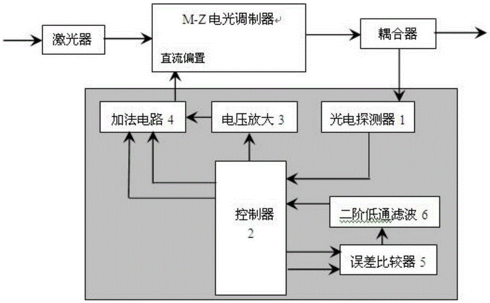
[0032] The device is composed of a photodetector (1), a controller (2), a voltage amplifier circuit (3), an addition circuit (4), an error comparator (5), and a second-order low-pass filter circuit (6). figure 2 . The connection relationship is: the input of the photodetector is connected to the output of the optocoupler, and the output is connected to the PAG input terminal of the controller; the PAG output terminal of the controller and the frequency multiplication output terminal of the jitter signal are connected to the input terminal of the error amplifier; the output of the error amplifier The terminal is connected to the input terminal of the second-order low-pass filter; the output terminal of the second-order low-pass filter is connected to the analog / digital conversion inpu...


PUM


Abstract

The invention relates to the field of optical transmission networks, and discloses a device and a method for controlling an offset working point of an electro-optic modulator. Especially in allusion to characteristics of high frequency and high speed of an organic polymer Mach-Zehnder electro-optic modulator, a purpose that the electro-optic modulator works at an optimal working point is achieved through adopting a programmable system on chip (PsoC) and a proportional-integral-differential (PID) control algorithm. The device is composed of a photoelectric detector (1), a controller (2), a voltage amplification circuit (3), an adding circuit (4), an error comparator (5) and a second-order low-pass filter circuit (6). According to the invention, a programmable computation ability of the PsoC is utilized, and the accurate PID control algorithm is adopted, thereby enabling the device to have the characteristics of simple structure, small size, easy implementation, high precision and ability of not relying on other external equipment. The device and the method disclosed by the invention solve problems that the control precision is low and that circuit are complex in the prior art, and realize high-precision control for the offset working point.

Description

technical field [0001] The invention relates to the field of optical transmission network, in particular to an electro-optic modulator bias operating point control system, which is used to provide a suitable DC bias voltage for the Mach-Zehnder electro-optic modulator. Background technique [0002] In communication systems, the role of Mach-Zehnder (M-Z) electro-optic modulators is to modulate electrical signals containing various information onto optical signals. Regardless of whether the electrical signal to be modulated is an analog signal or a digital signal, the M-Z electro-optic modulator must work in the best transmission characteristic range. In order to ensure that the M-Z electro-optic modulator works in the best characteristic region, an appropriate bias voltage must be applied to it. [0003] The purpose of the electro-optic modulator bias operating point control device is to provide sufficient voltage range for the electro-optic modulator; to provide a suitable...

Claims


Application Information

Patent Timeline
Patent Type & Authority Applications(China)
IPC IPC(8): G05B19/042G02F1/03
CPCG05B19/0423G02F1/0327G05B2219/1161
Inventor 高原唐普英李绍荣杨昕梅余梦璐
Owner UNIV OF ELECTRONICS SCI & TECH OF CHINA
Why Eureka
Try Eureka