Distributed power source optimal allocation method suitable for power distribution network

A distributed power supply and optimized configuration technology, applied in data processing applications, single-network parallel feeding arrangements, instruments, etc., can solve problems such as optimality dependence, premature phenomenon, and low efficiency

Active Publication Date: 2016-02-03
STATE GRID CORP OF CHINA +1
View PDF5 Cites 4 Cited by
  • Summary
  • Abstract
  • Description
  • Claims
  • Application Information

AI Technical Summary

Problems solved by technology

Analytical optimization methods are often derived based on simplified models, which may not be applicable to complex networks and load changes, or require a large number of iterative calculations to solve nonlinear programming models
However, the stochastic optimization method that introduces artificial inte

Method used


Image

  • Distributed power source optimal allocation method suitable for power distribution network
  • Distributed power source optimal allocation method suitable for power distribution network
  • Distributed power source optimal allocation method suitable for power distribution network

Examples


Embodiment Construction

[0038] The present invention will be further described below in conjunction with the accompanying drawings and embodiments.

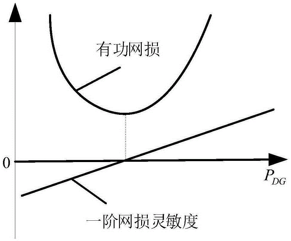
[0039] like figure 1 , the active network loss of the system and the capacity of a node connected to the distributed power supply present a "U" shape. This is because, when the distributed power supply capacity is small, the power transmission on the line is reduced, so that the active network loss of the system is reduced; and when the distributed power supply power exceeds a certain value, the power flow of the system will reverse, so Continuing to increase the access capacity of the distributed power generation will lead to an increase in the network loss of the system. A typical "U"-shaped curve is a quadratic function relationship, and its first-order derivative is not a linear function. Therefore, in the present invention, linear approximation is made to the first-order network loss sensitivity, which is also the basis for the application of the ...


PUM


Abstract

The invention relates to a distributed power source optimal allocation method suitable for a power distribution network. The method includes the following steps that: original data information is obtained, and the position of a balance node, the total capacity of distributed power source connection and the capacity step of the distributed power source connection are determined; when nodes are not connected into distributed power sources, the first-order grid loss sensitivity coefficients of the nodes are obtained; the node are separately connected into a capacity-set distributed power source, and the first-order grid loss sensitivity coefficients of the nodes are obtained; a sensitivity correction matrix is obtained; nodes with the minimum first-order grid loss sensitivity coefficients are connected with a capacity-step distributed power source; after the nodes are connected into the capacity-step distributed power source, the first-order grid loss sensitivity coefficients of the nodes are corrected through the sensitivity correction matrix, and single-step allocation schemes are recorded; and the previous step is repeated until the connection of the nodes to the distributed power sources achieves the total capacity of the distributed power source connection, and optimal allocation can be completed. With the distributed power source optimal allocation method adopted, a large quantity of power flow calculation can be eliminated, and the effectiveness and efficiency of optimization can be realized.

Description

technical field [0001] The invention relates to the field of optimal configuration of distributed power sources in power systems, in particular to a method for optimal configuration of distributed power sources suitable for distribution networks. Background technique [0002] The rapid development and application of distributed generation technology has attracted widespread attention from all over the world. The low investment cost of distributed power generation, environmental protection, flexible location, and energy diversity make it a good complement to large-scale power grids and become a strong support for large-scale power grids. Therefore, the power supply mode combining distributed power and large-scale power grid will be an inevitable trend of the future power grid. The access of distributed generation will have an important impact on the voltage level, system stability, power quality, network loss and other aspects of the distribution network. The degree of infl...

Claims


Application Information

Patent Timeline
IPC IPC(8): H02J3/38G06Q10/04G06Q50/06
CPCY02E40/70Y04S10/50
Inventor 武志刚杨晶晶林骞曹华明徐克政王娟娟孙延栋郭一飞
Owner STATE GRID CORP OF CHINA
Why Eureka
Try Eureka