Permanent magnet synchronous direct-drive motor

A technology of direct drive motor and permanent magnet synchronization, which is applied in the direction of suppressing electromagnetic interference, static parts of magnetic circuit, rotating parts of magnetic circuit, etc., can solve problems such as increased demagnetization inflection point, poor heat dissipation conditions, etc., and can reduce short-circuit current , improve the operating point, reduce the effect of rotor loss

Active Publication Date: 2016-02-03
NANJING ESTUN AUTOMATION CO LTD
View PDF5 Cites 4 Cited by
  • Summary
  • Abstract
  • Description
  • Claims
  • Application Information

AI Technical Summary

Problems solved by technology

[0007] Compared with the stator, the heat dissipation condition of the rotor is poor, and the increase of the eddy current loss of the rotor will increase the operating temperature of the permanent magnet, which will increase the demagnetization inflection point of the permanent magnet, and increase the risk of loss of magnetization and burning of the rail transit direct drive motor

Method used


Image

  • Permanent magnet synchronous direct-drive motor
  • Permanent magnet synchronous direct-drive motor
  • Permanent magnet synchronous direct-drive motor

Examples


Embodiment Construction

[0022] Below, refer to Figure 1 to Figure 8 , the present invention will be described in further detail.

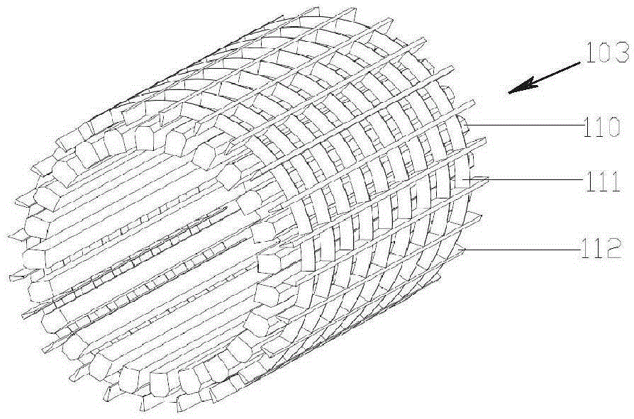
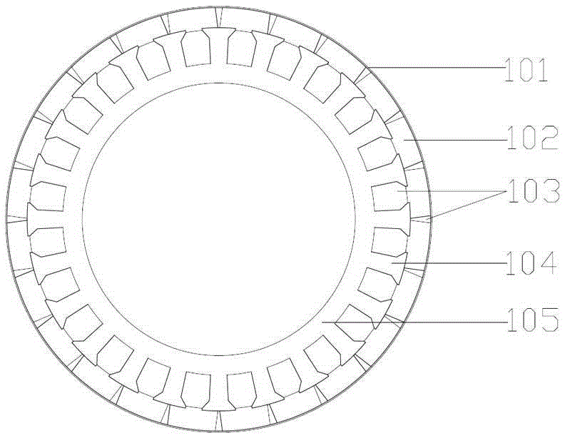
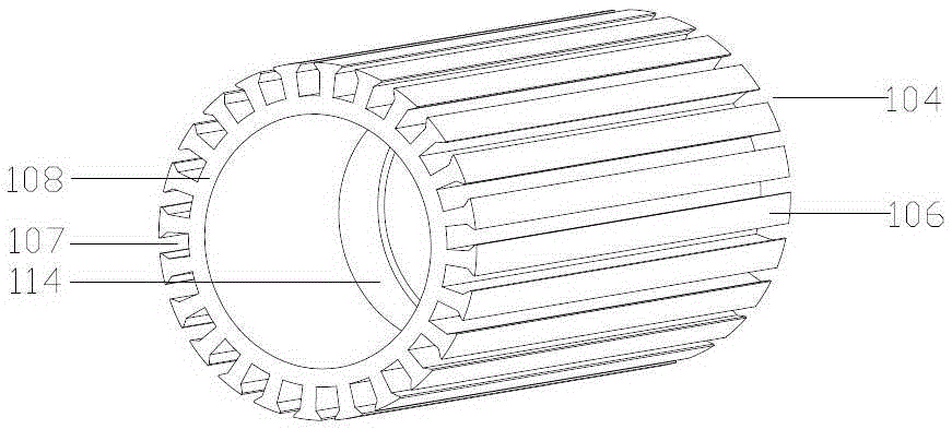
[0023] figure 1 It is a radial sectional view of a rotor of a permanent magnet synchronous direct drive motor of the present invention. Such as figure 1 As shown, the rotor includes: a glass ribbon 101 , a permanent magnet 102 , a rotor core 104 , and a shaft 105 . On the shaft 105, the rotor core 104 and one side of the non-magnetic metal end plate 113 (such as Figure 5 , 6 shown). A number of semi-closed slots 107 are uniformly formed along the outer circumferential surface of the rotor core, and the semi-closed slots are parallel to the shaft 105 . A permanent magnet 102 is mounted on the outer circumference of the rotor core 104 , and the contact surface between the permanent magnet 102 and the rotor core 104 is bonded with glue. Epoxy resin 103 is potted in the gaps between the permanent magnets and in the semi-closed slots. After the epoxy resin is filled,...


PUM


Abstract

The invention discloses a permanent magnet synchronous direct-drive motor. A rotor iron core sleeves a shaft. The outer periphery of the rotor iron core is evenly equipped with a plurality of semi-open slots. A plurality of permanent magnets are adhered to the outer periphery of the rotor iron core. Epoxy resin is arranged among the permanent magnets and among the semi-open slots through embedding. The two end faces of the rotor iron core are equipped with non-magnetic-conductive metal end plates. A stator iron core of a stator is evenly equipped with a plurality of open slots at the periphery. Notches of the open slots face the inner side of the stator, and stator windings are disposed in the open slots respectively. The notches of the open slots are provided with magnetic conductive blocks, and are plugged by the magnetic conductive blocks. The motor of the invention is increased in pass mass ratio, exhibits high structural reliability, is easy to manufacture, and can response quickly. The harmonic wave content of an air gap magnetic field of the permanent magnet motor and the rotor loss of the motor are reduced, the magnetic leakage coefficient and the reactance of the motor are increased, short circuit currents are minimized, the operating points of the permanent magnets are improved, and the reliability of the permanent magnet synchronous direct-drive motor is improved.

Description

technical field [0001] The invention relates to a permanent magnet synchronous direct drive motor, in particular to the structure of the rotor and the stator of the permanent magnet synchronous direct drive motor. Background technique [0002] Permanent magnet synchronous motors have the advantages of high efficiency, high power density, strong overload capacity, small size, and light weight. They have been widely used in rail transit and industrial automation in recent years. [0003] The traditional transmission mechanism adopts the scheme of high-speed permanent magnet synchronous motor acceleration and deceleration to realize low-speed direct drive operation, but there are problems such as low efficiency, high noise, high maintenance cost, and serious environmental pollution; and permanent magnet synchronous direct drive motor saves the intermediate transmission mechanism , has solved the above problems, and has gradually become a research hotspot in the field of rail tr...

Claims


Application Information

Patent Timeline
Patent Type & Authority Applications(China)
IPC IPC(8): H02K1/27H02K1/16H02K1/18H02K1/28H02K11/02
Inventor 董顶峰孔繁尘李卿安永乐吴波
Owner NANJING ESTUN AUTOMATION CO LTD
Why Eureka
Try Eureka