Rotor structure used for tangential permanent magnet direct current brushless motor, and tangential permanent magnet direct current brushless motor

A brushless motor, permanent magnet DC technology, applied in the direction of magnetic circuit shape/style/structure, magnetic circuit rotating parts, electrical components, etc., can solve problems such as large magnetic flux leakage coefficient, low overload capacity, complex structure and assembly , to achieve the effects of small magnetic flux leakage coefficient, high overload capacity and low manufacturing cost

Inactive Publication Date: 2016-02-03
NANJING KANGNI ELECTRONICS TECH
View PDF6 Cites 12 Cited by
  • Summary
  • Abstract
  • Description
  • Claims
  • Application Information

AI Technical Summary

Problems solved by technology

[0004] The technical problem solved by the present invention is that the rotor structure in the existing directional permanent magnet brushless DC motor has a relatively large magnetic flux leakage coefficient, low overload capacity, and complex structure and assembly

Method used


Image

  • Rotor structure used for tangential permanent magnet direct current brushless motor, and tangential permanent magnet direct current brushless motor
  • Rotor structure used for tangential permanent magnet direct current brushless motor, and tangential permanent magnet direct current brushless motor
  • Rotor structure used for tangential permanent magnet direct current brushless motor, and tangential permanent magnet direct current brushless motor

Examples


Embodiment Construction

[0024] The present invention will be further described below in conjunction with the accompanying drawings.

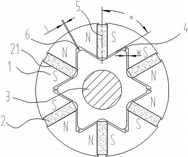
[0025] The rotor structure for the tangential permanent magnet brushless DC motor of the present invention, such as figure 1 The first embodiment shown includes a rotor core 1, a tangential permanent magnet 2 and a rotating shaft 3. The rotor core 1 is distributed with an even number of tangential permanent magnet slots 21 at equal intervals along the radial direction of the circumference. Adjacent tangential permanent magnet slots 21 A tangential permanent magnet 2 with opposite polarity is provided in the permanent magnet slot 21 to form a rotor pole N or S. The tangential permanent magnet slot 21 is connected or disconnected from the side near the air gap, and interval connection and disconnection can be used. The opening structure is staggered to keep the center of the rotor core 1 symmetrical. The side near the rotation axis of the tangential permanent magnet slot...


PUM


Abstract

The invention discloses a rotor structure used for a tangential permanent magnet direct current brushless motor, and the tangential permanent magnet direct current brushless motor. The rotor structure comprises a rotor iron core, tangential permanent magnets and a rotation shaft; an even number of tangential permanent magnet grooves are formed in the circumference of the rotor iron core radially at the equal intervals; the tangential permanent magnets with the opposite polarities are arranged in the adjacent tangential permanent magnet grooves; the tangential permanent magnets are connected with or disconnected from the near air gap side; the central symmetry of the rotor iron core is maintained; the sides, close to the rotation shaft, of the tangential permanent magnet grooves are communicated with flux-insulation grooves on the two sides of the tangential permanent magnet grooves; the near air gap side of the flux-insulation grooves and the central line of the corresponding tangential permanent magnet grooves extend outwardly at an angle of alpha; and a radially-distributed flux-insulation bridge is formed between the adjacent flux-insulation grooves. The rotor structure used for the tangential permanent magnet direct current brushless motor is simple and compact in structure, small in magnetic leakage factor, high in mechanical strength, convenient to produce, low in manufacturing cost, higher in resistance to demagnetization, and high in overload capacity, so that the tangential permanent magnet direct current brushless motor is higher in torque / current ratio, torque / volume ratio and motor efficiency; and therefore, the rotor structure used for the tangential permanent magnet direct current brushless motor, and the tangential permanent magnet direct current brushless motor are brighter in the application prospects.

Description

technical field [0001] The invention relates to the technical field of DC brushless motor components, in particular to a rotor structure for a tangential permanent magnet DC brushless motor and the motor thereof. Background technique [0002] The tangential permanent magnet brushless DC motor has a "magnetic concentration" effect, so it has a higher air gap flux density than the radial motor rotor structure, and the unique convexity of the tangential permanent magnet brushless DC motor The pole-effect ratio can generate a larger reluctance torque, so that the motor has a larger torque / current ratio, torque / volume ratio and field-weakening speed expansion characteristics, so it has been widely studied and applied. [0003] At present, the rotor structure in the tangential permanent magnet brushless DC motor generally has many limitations, as follows: (1) The magnetic flux leakage coefficient is relatively large, especially near the inner side of the rotating shaft, resulting ...

Claims


Application Information

Patent Timeline
Patent Type & Authority Applications(China)
IPC IPC(8): H02K29/00H02K1/27
Inventor 唐成文徐新艳
Owner NANJING KANGNI ELECTRONICS TECH
Why Eureka
Try Eureka