Point potential balance control method in three-level NPC inverter
A potential balance and control method technology, which is applied to electrical components, AC power input conversion to DC power output, output power conversion devices, etc., can solve the uncontrollable area of midpoint potential, uneven charging and discharging of capacitors, and increase the power switch. Tube switching frequency and other issues, to achieve the effect of expanding the range of possible values
- Summary
- Abstract
- Description
- Claims
- Application Information
AI Technical Summary
Problems solved by technology
Method used
Image

Examples
Embodiment 1
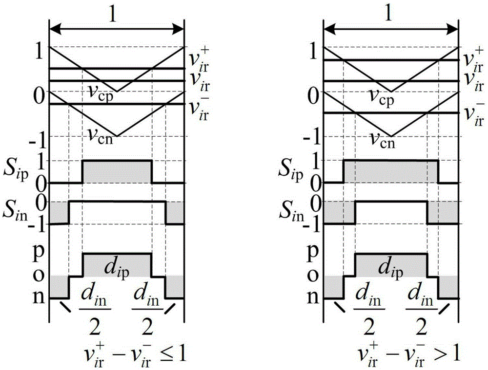
[0037] In the embodiment of the present invention, positive and negative modulation waves are obtained by decomposing the modulation wave of the three-phase reference voltage obtained by injecting the three-phase positive sequence voltage into the zero sequence voltage, and the decomposed positive and negative modulation wave constraints and midpoint potential balance are obtained condition. described as follows:
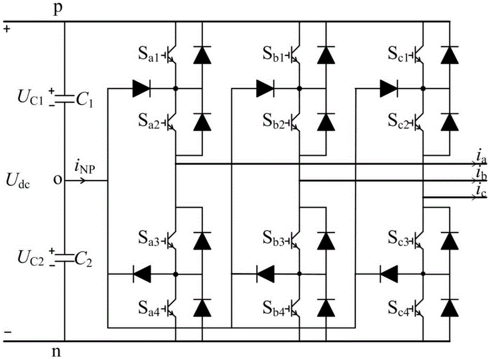
[0038] Three-level NPC inverter topology such as figure 1 As shown in the figure, U dc is the DC side voltage, U C1 , U C2 is the voltage of capacitors C1 and C2, i a i b i c is the three-phase load current. Each phase of the three-level NPC inverter has three switch states, taking phase a as an example, S a1 and S a2 Open, S a3 and S a4 When turned off, the output phase voltage is U dc / 2, set to state "p"; S a2 and S a3 Open, S a1 and S a4 When shutting down, the output phase voltage is 0, set to state "o"; S a3 and S a4 Open, S a1 and S a2 Whe...
Embodiment 2
[0125] In order to verify the effectiveness of this method, use Matlab / Simulink tools for simulation verification. Take U in the model dc =100V, capacitance C 1 =C 2 =1mF, fundamental frequency f 0 =50Hz, carrier frequency f s =5kHz, the load adopts resistive inductive load In the simulation, the method in this paper is compared with the existing single and double modulated wave methods respectively.
[0126] Figure 8 for m=0.7, When the traditional single modulation wave method, the existing double modulation wave method and the modulation wave, capacitor voltage and switch tube S of this method a1 The switching sequence vs. waveform. In the simulation, at t=0.252s, the modulation method adopted by the three-level NPC inverter is changed from the traditional single modulation wave method to the existing dual modulation method; after t=0.312s, this method is adopted. Depend on Figure 8 It can be seen that this method can effectively achieve midpoint potential bal...
PUM
 Abstract
Description
Claims
Application Information