Neutron source

A neutron source, ion source technology, applied in accelerators, DC voltage accelerators, electrical components, etc., can solve problems such as unfavorable production and installation, complex structure, etc., and achieve easy production and installation, small size, and high neutron yield. Effect

Inactive Publication Date: 2016-02-03
PEKING UNIV +1
View PDF6 Cites 13 Cited by
  • Summary
  • Abstract
  • Description
  • Claims
  • Application Information

AI Technical Summary

Problems solved by technology

[0003] In the prior art, the RFQ accelerator is generally applied to the neutron source in combination with the electron cyclotron or other components. The structure is relatively com

Method used


Image

  • Neutron source
  • Neutron source
  • Neutron source

Examples


Embodiment 1

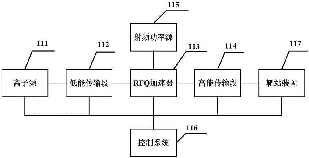
[0055] figure 1 A structural block diagram of a neutron source provided in Embodiment 1 of the present invention; figure 1 as shown,

[0056] The neutron source includes: an ion source 111 , a low-energy transmission section 112 , an RFQ accelerator 113 , a high-energy transmission section 114 , a radio frequency power source 115 , a control system 116 and a target station device 117 .

[0057]Described ion source 111 is connected with low-energy transmission section 112, is used to produce ion; Wherein, ion source 111 can adopt electron cyclotron resonance (Electron Cyclotron Resonanc, ECR) ion source or Penning source, the ion that produces is proton or deuterium ion, and ion exit energy is Tens of kiloelectron volts, the beam intensity is on the order of milliamps.

[0058] The low-energy transmission section 112 is connected to the RFQ accelerator 113 for adjusting the ion beam current;

[0059] The RFQ accelerator 113 is connected with the high-energy transmission sect...

Embodiment 2

[0069] Figure 4 It is a structural block diagram of a neutron source provided by Embodiment 2 of the present invention; each device is optimized on the basis of Embodiment 1 above. like Figure 4 As shown, the low-energy transmission section 112 includes: a first solenoid lens 1121, a first guide magnet 1122, a second guide magnet 1123 and a second solenoid lens 1124; wherein, the first solenoid lens 1121 is connected to the ion source 111 for focusing the ions to adjust the elliptic parameters of the ion beam; the first guiding magnet 1122 is connected to the first helical lens 1121 for focusing the ion beam in the X direction Adjustment; the second guide magnet 1123 is connected with the first guide magnet 1122 for adjusting the beam current of ions in the Y direction; the second solenoid lens 1124 is connected with the second guide magnet 1123 for use in Focusing is performed on the ion beam after the direction is adjusted, so as to adjust the ellipse parameter of the io...


PUM


Abstract

The invention discloses a neutron source, and the neutron source comprises an ion source, a low-energy transmission segment, an RFQ accelerator, a high-energy transmission segment, a radio frequency power source, a target station device, and a control system. The ion source is used for generating ions. The low-energy transmission segment is used for adjusting an ion beam. The RFQ accelerator is used for increasing the speed of the ion beam, so as to enable the energy of each ion to be within the range from 0.1MeV to 10MeV. The high-energy transmission segment is used for adjusting the ion beam after speed increase. The radio frequency power source is used for providing a radio frequency signal for the RFQ accelerator. The target station device is used for generating neutrons and leading the neutrons out. The control system is used for controlling the ion source, the low-energy transmission segment, the RFQ accelerator, the high-energy transmission segment, and the target station device. The neutron source can employ the independent RFQ accelerator, is small in size, is small in occupied space, is high in neutron yield, and is convenient for production and installation.

Description

technical field [0001] The invention belongs to the field of neutron production, in particular to a neutron source. Background technique [0002] The Radio Frequency Quadrupole (RFQ) accelerator was first proposed in 1970 by Kapuchinsky and Tepriakov, scientists of the Institute of High Energy Physics of the former Soviet Union. Focusing and longitudinal acceleration, because of its strong beam current, good quality, small size, easy to use and suitable for directly accelerating various ions from the ion source to the energy region of several MeV per nucleus, it is widely used in various accelerators Injectors, ion implanters, strong neutron sources, etc. [0003] In the prior art, the RFQ accelerator is generally applied to the neutron source in combination with the electron cyclotron or other components. The structure is relatively complicated, which is not conducive to production and installation. At present, a separate RFQ accelerator is applied to the neutron source T...

Claims


Application Information

Patent Timeline
IPC IPC(8): H05H13/00H05H7/02H05H6/00
Inventor 陆元荣郭之虞颜学庆朱昆高淑丽贾方健邹宇斌王智陈佳洱
Owner PEKING UNIV
Why Eureka
Try Eureka