Press-in riveting machine for automobile belt tensioner

A tensioner and belt technology, used in vehicle parts, transportation and packaging, manufacturing tools, etc., can solve the problems of various tooling, increase production costs, and high labor costs, reduce scrap rate, reduce labor costs, and improve The effect of production efficiency

Active Publication Date: 2017-06-13
WUXI YONGKAIDA GEAR
View PDF6 Cites 0 Cited by
  • Summary
  • Abstract
  • Description
  • Claims
  • Application Information

AI Technical Summary

Problems solved by technology

[0002] The assembly of automobile belt tensioners generally adopts assembly line assembly, with one operator for each station, many operators, various tooling, waste of labor, many errors caused by human factors, and low production efficiency
During assembly, such as Figure 5 As shown, tensioning arm 4', housing 3', positioning shaft, damping assembly, spring, pulley, etc. need to be pre-assembled into pulley tensioner pre-assembly 2' (hereinafter referred to as pre-assembly), and then the front wheel needs to be 1′ is press-fitted and riveted on the upper end of the positioning shaft of the pre-assembled part 2′. After the riveting, it is necessary to check whether the riveting is in place, the torque after pressing, and the size of the riveting mouth. The existing assembly line method requires Multiple stations, multiple operators, multiple sets of fixtures, detection devices and riveting tools, low production efficiency, high labor costs, manual pressing and riveting of the tensioning arm, due to the existence of human factors, it is easy to produce incorrect Qualified products, and the transfer and transportation between each process will increase the workload, affect the production efficiency and increase the production cost

Method used


Image

  • Press-in riveting machine for automobile belt tensioner
  • Press-in riveting machine for automobile belt tensioner
  • Press-in riveting machine for automobile belt tensioner

Examples


Embodiment Construction

[0018] The specific implementation manners of the present invention will be further described in detail below in conjunction with the accompanying drawings.

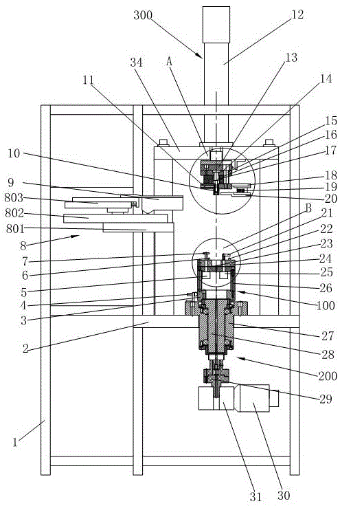
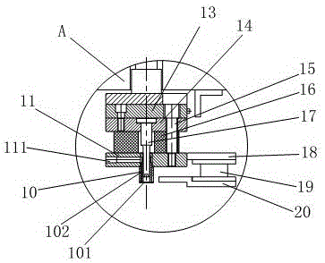
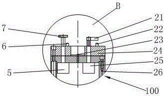
[0019] Such as Figure 1~4 As shown, the present invention includes a frame 1 and a workbench 2, the workbench 2 is horizontally arranged on the frame 1, the swivel seat 3 is arranged above the workbench 2, and the swivel seat 3 is connected to a motor drive mechanism 200 arranged below the workbench 2 . The motor drive mechanism 200 includes a bearing seat 27 fixedly connected to the workbench 2. The axis of the bearing seat 27 is perpendicular to the workbench 2. The main shaft 28 is rotatably installed in the bearing seat 27 through the bearing. The upper end of the main shaft 28 is connected to the rotating seat 3. The main shaft 28 The lower end of the lower end is connected to the reducer 31 and the motor 30 through the coupling 29. The motor 30 is connected to the reducer 31 and drives the rotating base 3 to rota...


PUM


Abstract

The invention relates to a special press-in riveting machine for an automobile belt tensioner, which is characterized in that a rotating seat is connected to a motor drive mechanism, and a workpiece positioning seat is coaxially arranged on the rotating seat; the workpiece positioning seat includes a seat cylinder and a positioning plate, two The compression cylinder is set in the seat tube, the first positioning pin and the second positioning pin are set on the positioning plate, the circular pressure plate and the V-shaped pressure plate are respectively connected to the piston rod of the compression cylinder; the upper part of the workpiece positioning seat is coaxially provided with a pressure riveting Mechanism, riveting mechanism includes electronic press, bottom plate, fixed plate, tendon plate, riveting head and pressure sleeve; one side of the unloading plate is equipped with a torque sensor and a stopper; one side of the workpiece positioning seat is movable 3D intelligent Measuring sensors. The invention has a simple and compact structure, can complete the pressing, riveting and measuring of the tensioning arm at one time, improves the automation level, reduces the labor cost, improves the production efficiency and the qualified rate of products, and reduces the production cost.

Description

technical field [0001] The invention relates to a special equipment, in particular to a special machine for pressing in and riveting an automobile belt tensioner. Background technique [0002] The assembly of automobile belt tensioners generally adopts assembly line assembly, with one operator for each station, many operators, various tooling, waste of labor, many errors caused by human factors, and low production efficiency. During assembly, such as Figure 5 As shown, tensioning arm 4', housing 3', positioning shaft, damping assembly, spring, pulley, etc. need to be pre-assembled into pulley tensioner pre-assembly 2' (hereinafter referred to as pre-assembly), and then the front wheel needs to be 1′ is press-fitted and riveted on the upper end of the positioning shaft of the pre-assembled part 2′. After the riveting, it is necessary to check whether the riveting is in place, the torque after pressing, and the size of the riveting mouth. The existing assembly line method req...

Claims


Application Information

Patent Timeline
Patent Type & Authority Patents(China)
IPC IPC(8): B21D53/88B21D39/00B21C51/00
Inventor 糜建鸿范晓
Owner WUXI YONGKAIDA GEAR
Why Eureka
Try Eureka