Photocuring 3D printer and working method thereof

A 3D printer and working method technology, applied in the direction of additive processing, etc., can solve the problems of large volume, unfavorable large-scale promotion, high manufacturing cost, etc., and achieve the effect of small size, conducive to large-scale promotion, and low manufacturing cost

Inactive Publication Date: 2016-02-10
BONA YUNZHI TIANJIN TECH
View PDF4 Cites 4 Cited by
  • Summary
  • Abstract
  • Description
  • Claims
  • Application Information

AI Technical Summary

Problems solved by technology

[0003] At present, the light-curing 3D printers of the existing technology are mainly based on laser galvanometer and DLP digital light processing techno

Method used


Image

  • Photocuring 3D printer and working method thereof
  • Photocuring 3D printer and working method thereof

Examples


Example Embodiment

[0017] Example 1

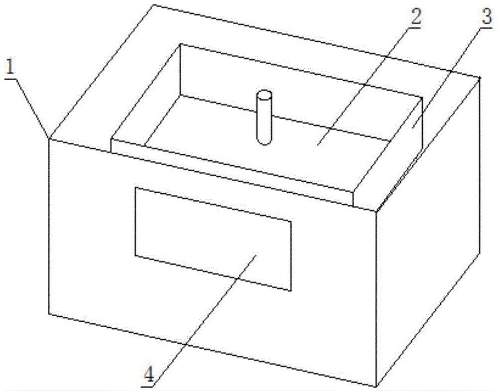
[0018] Such as Figure 1-2 As shown, a light-curing 3D printer includes a body 1, a printing material chute 3 and a printing platform 2 are arranged in the body 1, and a digital control screen 4 for controlling the digital pathway of a digital program to ultraviolet rays is also arranged in the body 1. The lower part of the printing material tank 3 is provided with a control board 5, and the lower part of the control board 5 is provided with a light source board 7 which is arrayed with ultraviolet light sources, and the bottom of the inner surface of the printing material tank 3 is provided with an oxygen permeable film.

[0019] A working method of a light-curing 3D printer. When the ultraviolet light source is irradiated, the digital program in the control screen 4 realizes the digital control of the digital channel of the ultraviolet, so that the required image is projected according to the digital program control, and the encoded image is irradiated to the pr...

Example Embodiment

[0020] Example 2

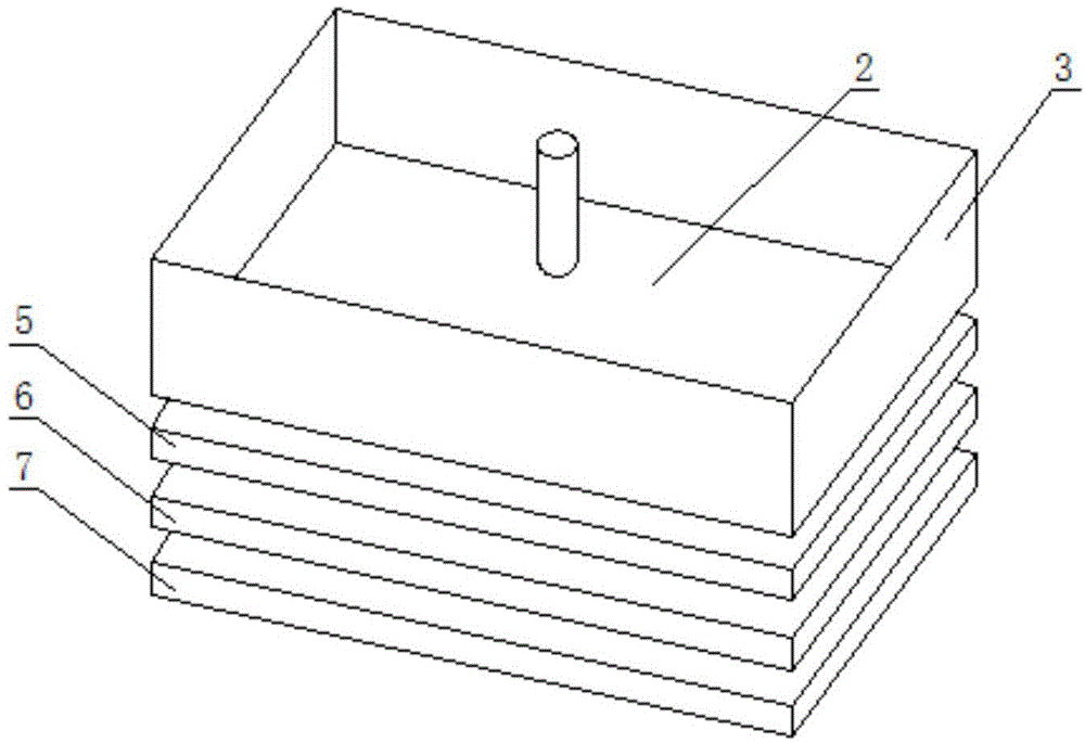
[0021] Such as Figure 1-2 As shown, a light-curing 3D printer includes a body 1, a printing material chute 3 and a printing platform 2 are arranged in the body 1, and a digital control screen 4 for controlling the digital pathway of a digital program to ultraviolet rays is also arranged in the body 1. The control panel 4 is an LCD control panel. The lower part of the printing material tank 3 is provided with a control panel 5, the lower part of the control panel 5 is provided with a diffuser panel 6, a light source plate 7 is arranged under the diffuser panel 6, and the light source plate 7 is arrayed. Ultraviolet light sources are arranged, and the bottom of the inner surface of the printing material tank 3 is provided with an oxygen permeable membrane.

[0022] A working method of a light-curing 3D printer. When the ultraviolet light source is irradiated, the digital program in the control screen 4 realizes the digital control of the digital channel of the ul...


PUM

PropertyMeasurementUnit
Wavelengthaaaaaaaaaa

Abstract

A photocuring 3D printer is technically characterized by comprising a printer body; a printing material tank and a printing platform are arranged in the printer body; a control screen used for conducting digital control on a digital path of ultraviolet by means of controlling a digital program is further arranged in the printer body; a control panel is arranged under the printing material tank; a light source plate is arranged under the control panel; ultraviolet light sources are arranged on the light source plate in an arrayed mode; an oxygen permeation membrane is arranged at the bottom of the inner surface of the printing material tank. A working method of the photocuring 3D printer comprises the steps that when the ultraviolet light sources illuminate, digital control over the digital path of the ultraviolet is achieved through the digital program in the control screen, so that a required image is controlled to be projected according to the digital program; and the encoded image is projected to the bottom of the printing material tank, so that photosensitive resin in the printing material tank is cured, and finally the photosensitive resin is cured onto the printing platform. By the adoption of the technical scheme, the size of the photocuring 3D printer is small, the printing speed and the printing area are increased, the manufacturing cost is low, and large-scale popularization is facilitated.

Description

technical field [0001] The invention relates to the technical field of 3D printing devices, in particular to a light-curing 3D printer and its working method. Background technique [0002] 3D printer, also known as three-dimensional printer, is a kind of additive manufacturing technology, that is, a machine of rapid prototyping technology. It is based on a digital model file and uses special wax, powdered metal or plastic and other bondable materials. Three-dimensional objects are created by printing layers of adhesive materials. [0003] At present, the light-curing 3D printers in the prior art are mainly based on laser galvanometer and DLP digital light processing technology. The equipment manufactured by the two technologies is large in size and high in manufacturing cost, which is not conducive to large-scale promotion. Contents of the invention [0004] In order to solve the above problems, the present invention provides a photocuring 3D printer and its working metho...

Claims


Application Information

Patent Timeline
IPC IPC(8): B29C67/00B33Y50/02
Inventor 徐立峥
Owner BONA YUNZHI TIANJIN TECH
Why Eureka
Try Eureka