Drill bit for constructing cast-in-situ bored pile and hole forming method using same

A technique for drilling cast-in-situ piles and drill bits, which is applied in the direction of drill bits, drilling tools, and sheet pile walls, etc., which can solve the problems of troublesome and laborious replacement process, buried drill bits, and poor operability, so as to achieve fast construction process and save time cost, cost reduction effect

Active Publication Date: 2016-02-10
浙江易通特种基础工程股份有限公司
View PDF5 Cites 4 Cited by
  • Summary
  • Abstract
  • Description
  • Claims
  • Application Information

AI Technical Summary

Problems solved by technology

[0005] However, although sinking into the casing is beneficial to drilling, within the height range of the casing, this part of the sandy soil body between the casing and the pile hole may still collapse, and there is still sediment, which buries the drill bit and drill pipe, and cannot A series of problems such as lowering the reinforcement cage smoothly and affecting the quality of the pile body, etc., in order to completely eradicate the above-mentioned disadvantages, someone proposed the technical idea of ​​using drill bits of two sizes, one large and one small, that is, first use the large drill bit to drill at the height of the casing and the diameter of the casing. Use a small drill bit to drill a small hole with the same diameter as the bored pile design
Yet the actual operability of above-mentioned assumption is not strong, and this is because two kinds of drill bits need to be prepared for each construction, which increases the construction cost, and the drill bit needs to be mentioned outside the hole every time, and then the whole drill bit is removed from the drilling rig. After unscrewing and replacing a new drill bit, the overall weight of the drill bit itself is not light, and it will be heavier after being stuck with mud, which makes the replacement process bothersome and laborious, very inconvenient, and further delays the work process, so no matter from the perspective of time cost and economic cost The loss outweighs the gain

Method used


Image

  • Drill bit for constructing cast-in-situ bored pile and hole forming method using same
  • Drill bit for constructing cast-in-situ bored pile and hole forming method using same
  • Drill bit for constructing cast-in-situ bored pile and hole forming method using same

Examples


Embodiment Construction

[0028] The present invention will be further described below in conjunction with the accompanying drawings and specific embodiments.

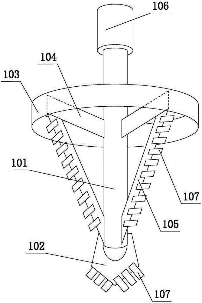
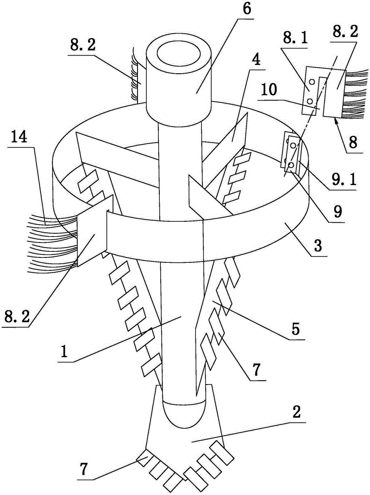
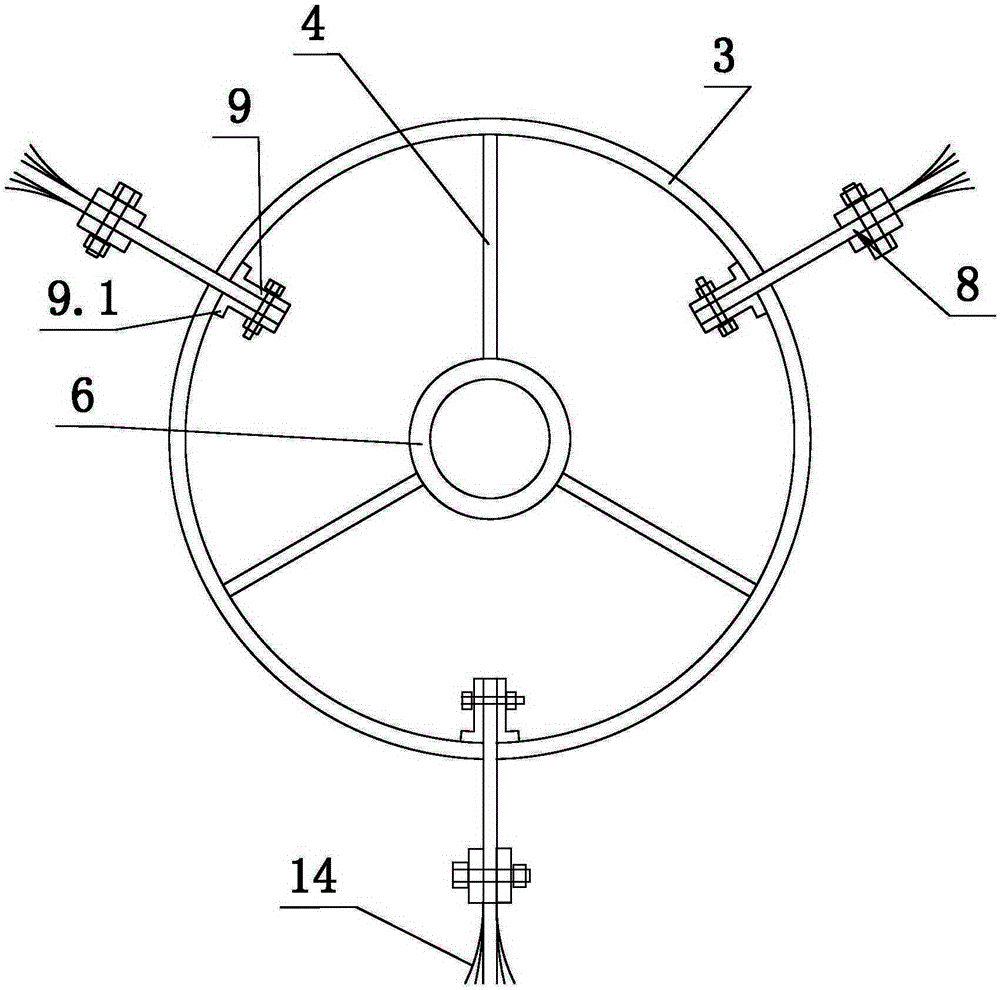
[0029] like figure 2 , image 3 , Figure 4 Shown, the present invention is used for the drill bit of construction bored cast-in-place pile, and it comprises hollow foundation bar 1, drill tip 2, back-up ring 3, a plurality of connecting plates 4 and scraper 5 identical with connecting plate 4 number. In this embodiment, there are three connecting plates 4 and three scrapers 5 .

[0030] The top of the base rod 1 is provided with a connecting part 6; specifically, the drill rod of the drilling rig is provided with a male buckle and the base rod 1 of the drill bit is provided with a female buckle, and both male and female are tightened and connected, and the described connecting part 6 is the female buckle.

[0031] The inner ends of the three connecting plates 4 are all welded on the base bar 1 and distributed evenly along the circumference...


PUM


Abstract

The invention discloses a drill bit for constructing a cast-in-situ bored pile and a hole forming method. The drill bit is provided with a detachable mud scrapping assembly, the mud scrapping assembly comprises mud scrapping plates (8) and installing plates (9), the installing plates (9) are welded to the inner circumferential face of a check ring (3), a steel brush (14) is arranged at the outer side of each mud scrapping part (8.2), the mud scrapping plates (8) are hooked and hung on the check ring (3) through clamping grooves (10), and an installing part (8.1) of each mud scrapping plate (8) is located between two corresponding installing plates (9) in the same set and fixed to the corresponding installing plates (9) at the two sides through threaded connection. The hole forming method is characterized in that in the drilling process, the mud scrapping plates (8) are installed on the check ring (3) to drill a big hole matched with a pile casing in size, and then the mud scrapping plates (8) are dismantled to drill a small hole, wherein the size of the small hole is matched with the design size of the cast-in-situ bored pile. By means of the drill bit and the hole forming method, sandy soil between the pile casing and the pile hole can be effectively drilled away without substantially increasing time and economic cost.

Description

technical field [0001] The invention relates to the field of pile foundation construction, in particular to a drill bit for constructing bored piles and a hole-forming method using the drill bit. Background technique [0002] Concrete bored piles have become a popular choice for domestic and foreign buildings (structures), especially large buildings (structures) such as bridges, The preferred foundation form for oil tanks, liquefied natural gas tanks, and nuclear power plants. The main construction process of concrete bored piles includes: forming holes, lowering steel cages, and pouring concrete. In the above-mentioned main construction process, hole forming is the key link. During the hole forming process, a three-wing scraper drill bit is usually used to drill into the formation. [0003] like figure 1 As shown, the three-wing scraper drill bit of the prior art includes a hollow base rod 101, a drill tip 102, a retaining ring 103, three connecting plates 104 and three...

Claims


Application Information

Patent Timeline
Patent Type & Authority Applications(China)
IPC IPC(8): E21B10/62E21B12/06E02D5/38
Inventor 付连红王慧荣向飞沈海姣巫晓林胡国斌韩国华汝宏祥
Owner 浙江易通特种基础工程股份有限公司
Why Eureka
Try Eureka