
High-temperature flue gas dust removal and waste heat utilization system of metallurgical furnace

A high-temperature flue gas and metallurgical furnace technology, applied in the field of metallurgical energy saving, can solve the problems of reducing the economic value of the waste heat system, increasing the investment of the waste heat system, and the large dust content of the flue gas, so as to prevent jamming, reduce the discharge temperature, and achieve high exchange rate. The effect of thermal efficiency

Inactive Publication Date: 2016-02-10
马忠华
View PDF0 Cites 7 Cited by
  • Summary
  • Abstract
  • Description
  • Claims
  • Application Information

AI Technical Summary

Problems solved by technology

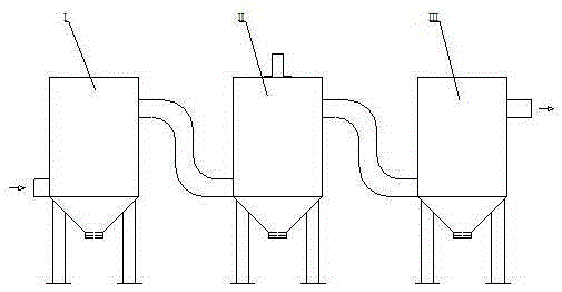
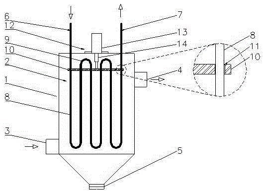
[0003] The technical problem to be solved by the present invention is: in order to solve the problem that the flue gas of the existing metallurgical furnace has a large amount of dust, when using the waste heat boiler with water tubes, the heat exchange effect in the early stage is relatively good. More and more smoke and dust will accumulate on the wall, resulting in a decrease in heat exchange efficiency, which relatively reduces the economic value of the waste heat system and increases the investment of the waste heat system. The present invention provides a high-temperature flue gas dedusting and waste heat utilization In the system, a set of waste heat utilization device is installed between the two electrostatic precipitators. The waste heat utilization device drives the dust removal plate to move up and down through the hydraulic cylinder to scrape off the smoke and dust on the vertical tube wall of the heat exchange tube, so that It can continuously maintain a high heat exchange efficiency, fully recover waste heat, and improve the economic value of the waste heat system

Method used


Image

  • High-temperature flue gas dust removal and waste heat utilization system of metallurgical furnace
  • High-temperature flue gas dust removal and waste heat utilization system of metallurgical furnace

Examples


Embodiment Construction

[0012] The present invention is described in further detail now in conjunction with accompanying drawing. These drawings are all simplified schematic diagrams, which only illustrate the basic structure of the present invention in a schematic manner, so they only show the configurations related to the present invention.

[0013] Such as figure 1 , figure 2 As shown, a metallurgical furnace high-temperature flue gas dedusting and waste heat utilization system includes a first-stage electric precipitator I, a waste heat utilization device II, and a second-stage electric precipitator III connected in sequence. The waste heat utilization device II includes a heat exchange box 1 and a vertical The heat exchange tubes 2 are directly arranged in the heat exchange box 1. The heat exchange box 1 has an air inlet 3, an air outlet 4, and a dust collection port 5 arranged at the bottom of the heat exchange box 1. The water inlet 6 of the heat exchange tube 2 And the water outlet 7 is ar...


PUM


Abstract

The invention relates to a high-temperature flue gas dust removal and waste heat utilization system of a metallurgical furnace. The system comprises a first-stage electric precipitator, a waste heat utilization device and a second-stage electric precipitator which are sequentially communicated, wherein the waste heat utilization device comprises a heat exchange tank and a heat exchange tube row; the heat exchange tube row is sleeved with a dedusting board; multiple through holes are formed in the dedusting board; vertical tubes of the heat exchange tube row penetrate through the through holes and are in sliding connection with the through holes of the dedusting board; a hydraulic cylinder is fixedly arranged on the top of the heat exchange tank; a cylinder barrel of the hydraulic cylinder is fixed to the top of the heat exchange tank; a piston rod of the hydraulic cylinder penetrates through the top of the heat exchange tank and is fixedly connected with the dedusting board inside the heat exchange tank. By means of the high-temperature flue gas dust removal and waste heat utilization system of the metallurgical furnace, the hydraulic cylinder drives the dedusting board to vertically move, smoke of the tube walls of the vertical tubes of the heat exchange tube tow is scraped, the higher heat exchange efficiency can be kept continuously, waste heat is sufficiently recycled, and the economic value of the waste heat system is improved.

Description

technical field [0001] The invention relates to the technical field of metallurgical energy saving, in particular to a high-temperature flue gas dedusting and waste heat utilization system of a metallurgical furnace. Background technique [0002] In the prior art, the purification device for the flue gas of the metallurgical furnace is the flue gas generating equipment of the metallurgical furnace, the waste heat utilization facility, and the dust collector are connected in sequence through pipelines. The waste heat utilization facility usually used at present is a heat exchanger, which is a device that can not only reduce the temperature of the flue gas, but also utilize the high-temperature flue gas to achieve the purpose of heat exchange. Water column waste heat boiler and regenerative heat pipe heat exchanger are used to recover the waste heat of metallurgical furnace flue gas and generate saturated steam, etc. Because the flue gas temperature of metallurgical furnace f...

Claims


Application Information

Patent Timeline
Patent Type & Authority Applications(China)
IPC IPC(8): F27D17/00F28G1/08
CPCY02P10/25
Inventor 马忠华
Owner 马忠华
Learn More