
Metallurgical furnace waste heat utilizing device

A metallurgical furnace and waste heat technology, applied in furnaces, waste heat treatment, furnace components, etc., can solve problems such as large dust content in flue gas, reduced heat exchange efficiency, and increased investment in waste heat systems, achieving high heat exchange efficiency and improving economic efficiency value effect

Inactive Publication Date: 2016-02-10
马忠华
View PDF0 Cites 2 Cited by
  • Summary
  • Abstract
  • Description
  • Claims
  • Application Information

AI Technical Summary

Problems solved by technology

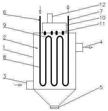
[0003] The technical problem to be solved by the present invention is: in order to solve the problem that the flue gas of the existing metallurgical furnace has a large amount of dust, when using the waste heat boiler with water tubes, the heat exchange effect in the early stage is relatively good. More and more smoke and dust will accumulate on the wall, resulting in a decrease in heat exchange efficiency, which relatively reduces the economic value of the waste heat system and increases the investment of the waste heat system. The invention provides a waste heat utilization device for metallurgical furnaces. The sealed water tank on the top of the tank is supplied with water. With the assistance of the air pump, the water in the sealed water tank is sprayed from the water nozzle to wash the smoke and dust on the vertical tube wall of the heat exchange tube so that it can continuously maintain a high temperature. High heat exchange efficiency, fully recovering waste heat, and improving the economic value of the waste heat system

Method used


Image

  • Metallurgical furnace waste heat utilizing device

Examples


Embodiment Construction

[0010] The present invention is described in further detail now in conjunction with accompanying drawing. These drawings are all simplified schematic diagrams, which only illustrate the basic structure of the present invention in a schematic manner, so they only show the configurations related to the present invention.

[0011] Such as figure 1 As shown, a metallurgical furnace waste heat utilization device includes a heat exchange box 1 and a heat exchange column tube 2 vertically arranged in the heat exchange box 1. The heat exchange box 1 has an air inlet 3, an air outlet 4 and a heat exchange The dust collection port 5 at the bottom of the box 1, the water inlet 6 and the water outlet 7 of the heat exchange tube 2 are arranged on the top of the heat exchange box 1, and the heat exchange tube 2 includes several vertical tubes 8 and a connecting tube for connecting the vertical tubes 8. The top of the heat exchange box 1 is provided with a sealed water tank 10, the lower pa...


PUM


Abstract

The invention relates to a metallurgical furnace waste heat utilizing device which comprises a heat exchange box and a heat exchange tube nest vertically arranged in the heat exchange box. The heat exchange box is provided with an air inlet, an air outlet and a dust collecting opening in the bottom of the heat exchange box. A water inlet and a water outlet of the heat exchange tube nest are located at the top of the heat exchange box, and the heat exchange tube nest comprises a plurality of vertical tubes and bent tubes used for connecting the vertical tubes. A sealed water tank is arranged at the top of the heat exchange box, and the lower portion of the sealed water tank is communicated with the interior of the heat exchange box through a plurality of water nozzles. The upper portion of each vertical tube is at least provided with one water nozzle, and an air pump is arranged on the top of the sealed water tank. According to the metallurgical furnace waste heat utilizing device, water is supplied through the sealed water tank on the top of the heat exchange box, under the assistance of the air pump, the water in the sealed water tank is sprayed out from the water nozzles so as to flush away dust on the walls of the vertical tubes of the heat exchange tube nest, high heat exchange efficiency of the heat exchange tube nest can be continuously maintained, waste heat is fully recovered, and the economic value of a waste heat system is increased.

Description

technical field [0001] The invention relates to the technical field of metallurgical energy saving, in particular to a waste heat utilization device of a metallurgical furnace. Background technique [0002] In the prior art, the purification device for the flue gas of the metallurgical furnace is the flue gas generating equipment of the metallurgical furnace, the waste heat utilization facility, and the dust collector are connected in sequence through pipelines. The waste heat utilization facility usually used at present is a heat exchanger, which is a device that can not only reduce the temperature of the flue gas, but also utilize the high-temperature flue gas to achieve the purpose of heat exchange. Water column waste heat boiler and regenerative heat pipe heat exchanger are used to recover the waste heat of metallurgical furnace flue gas and generate saturated steam, etc. Because the flue gas temperature of metallurgical furnace fluctuates violently and the dust content...

Claims


Application Information

Patent Timeline
Patent Type & Authority Applications(China)
IPC IPC(8): F27D17/00
CPCY02P10/25Y02P80/15
Inventor 马忠华
Owner 马忠华
Learn More