
In-situ detection method of polarization aberration of projection objective lens of lithography machine

A technology of projection objective lens and lithography machine, which is applied in the field of lithography machine, and can solve the problems of small number of aberrations, low measurement accuracy of polarization attenuation and polarization delay components, etc.

Active Publication Date: 2017-05-24
SHANGHAI INST OF OPTICS & FINE MECHANICS CHINESE ACAD OF SCI
View PDF2 Cites 0 Cited by
  • Summary
  • Abstract
  • Description
  • Claims
  • Application Information

AI Technical Summary

Problems solved by technology

However, in the prior art 1, only one polarization illumination method is used in the calibration and measurement process, and the sensitivity coefficients of each polarization aberration obtained by calibration are linearly correlated, which ultimately leads to a small number of detectable aberrations and low precision.
Prior art 2 requires different polarization aberration characterization and detection methods for different polarization aberration components, the process is complex, and the measurement accuracy of polarization attenuation and polarization delay components is low

Method used


Image

  • In-situ detection method of polarization aberration of projection objective lens of lithography machine
  • In-situ detection method of polarization aberration of projection objective lens of lithography machine
  • In-situ detection method of polarization aberration of projection objective lens of lithography machine

Examples


Embodiment Construction

[0077] The present invention will be further described below in conjunction with the examples and drawings, but the examples should not limit the protection scope of the present invention.

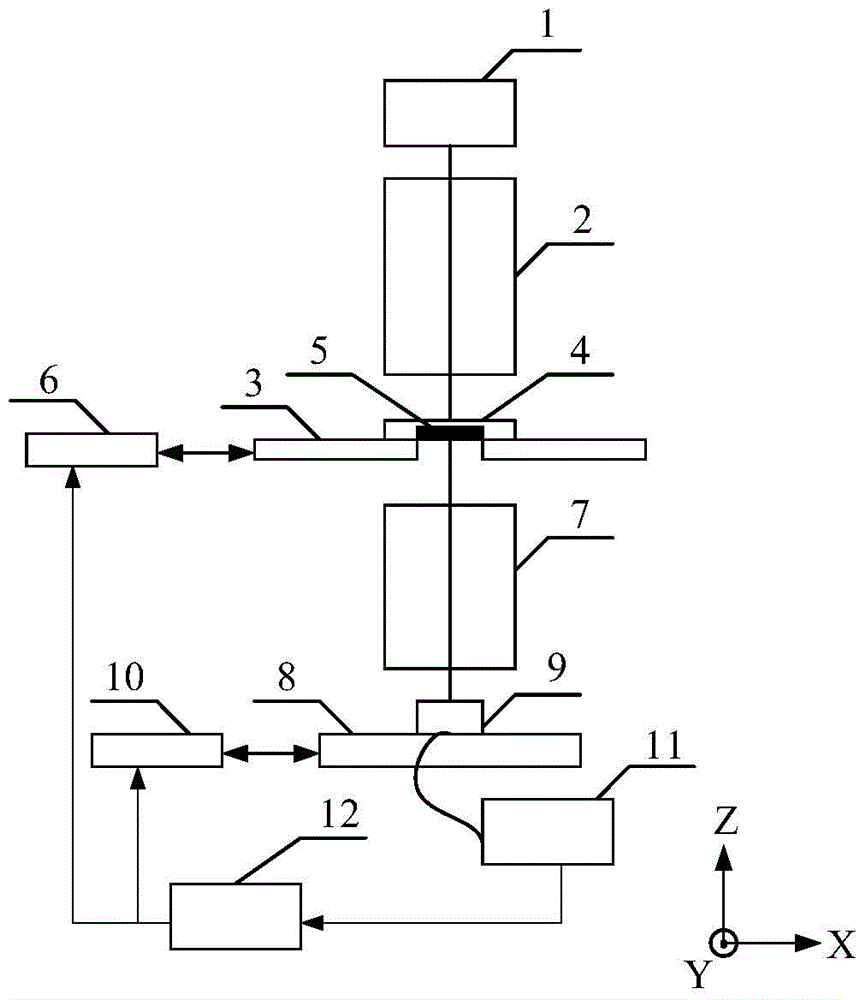
[0078] figure 1 Schematic diagram of the structure of the projection objective polarization aberration detection system used in the present invention, including a light source 1 that generates an illumination beam, an illumination system that adjusts the illumination mode (including polarization illumination mode) and partial coherence factor of the beam emitted by the light source 1 and makes the beam uniformly illuminated 2. A mask table equipped with a mask and using a positioning system 6 to achieve precise positioning 3. A mask 4 including a polarization aberration detection mark 5. A projection objective lens with large numerical aperture capable of imaging the mask pattern and having an adjustable numerical aperture 7. A workpiece table 8 capable of carrying silicon wafers and using...


PUM


Abstract

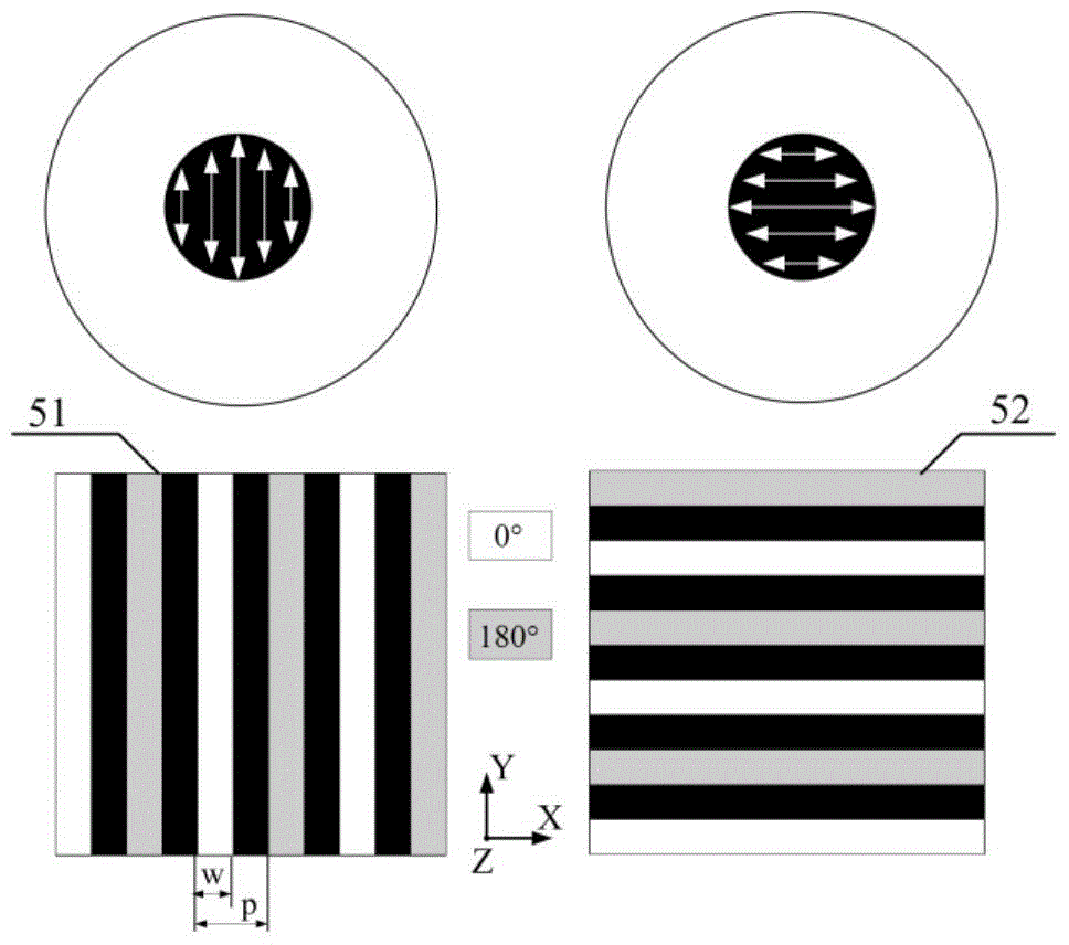
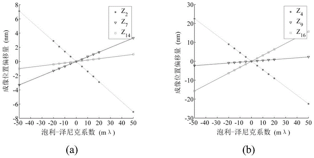
An in-situ detection method for projection objective polarization aberration of a photoetching machine is disclosed. A detection system used by the method comprises a light source, an illuminating system, a mask table, masks including detection labels, a projection objective, a workpiece table, an image sensor, a positioning system for the mask table and the workpiece table, a data processing system and a feedback control system. According to the in-situ detection method, a Pauli-Zernike characterization method for the polarization aberration is adopted; two linear polarization aberration illuminating modes are combined; the imaging position offset and the optimal focal plane offset of the detection mark space image are measured by the image sensor; and the polarization aberration of the projection objective is calculated according to a marked polarization aberration sensitivity coefficient. The in-situ detection method for the projection objective polarization aberration of the photoetching machine has the characteristics of simple and rapid detection process, and high precision of the aberration detection, so that the in-situ detection method is suitable for detecting the polarization aberration of projection objectives with large numerical apertures or extra-large numerical apertures.

Description

technical field [0001] The invention relates to a lithography machine, in particular to an in-situ detection method for polarization aberration of a projection objective lens of a lithography machine. Background technique [0002] The projection objective lens is one of the core components of the lithography machine system. The polarization aberration of the projection objective lens will cause the feature size error of the lithography image, the offset of the imaging position and the offset of the best focal plane, etc., resulting in the deterioration of the image quality and process window. These undesirable effects of polarization aberrations cannot be ignored when high NA projection objectives and polarized illumination are employed. A fast and effective detection method for polarization aberration is a prerequisite for reducing and controlling its adverse effects, which is of great significance to the improvement of lithography imaging quality. [0003] The projection...

Claims


Application Information

Patent Timeline
Patent Type & Authority Patents(China)
IPC IPC(8): G03F7/20
Inventor 沈丽娜王向朝李思坤闫观勇诸波尔张恒孟泽江
Owner SHANGHAI INST OF OPTICS & FINE MECHANICS CHINESE ACAD OF SCI
Learn More