Novel RFID circularly polarized antenna

A circularly polarized antenna and microstrip line technology, applied in the field of antennas, can solve the problems of limited application occasions, no circular polarization index axial ratio data, etc., to reduce the surface area of ​​the antenna, improve the circular polarization performance, reduce the The effect of taking up space

Inactive Publication Date: 2016-02-10
UNIV OF ELECTRONICS SCI & TECH OF CHINA
View PDF2 Cites 10 Cited by
  • Summary
  • Abstract
  • Description
  • Claims
  • Application Information

AI Technical Summary

Problems solved by technology

In addition, the article does not give the data of the axial ratio of the circular polarization index
[0005] The literature "CompactPrintedYagiAntennaforHandheldUHFRFIDReader" (published journal: 2011InternationalConference; date of publication: 2011; author: SivajiKaki, Dr.TapasChakravarty) realizes two-way radiation through the improved Yagi structure, but both directions are linearly polarized radiation, which limits its application
[0006] At present, there have been reported methods that can achieve circular polarization and bidirectional radiation, but there are few methods that can simultaneously achieve bidirectional radiation and circular polarization

Method used


Image

  • Novel RFID circularly polarized antenna
  • Novel RFID circularly polarized antenna
  • Novel RFID circularly polarized antenna

Examples


Embodiment Construction

[0026] The present invention will be further described in detail below in conjunction with the accompanying drawings and embodiments.

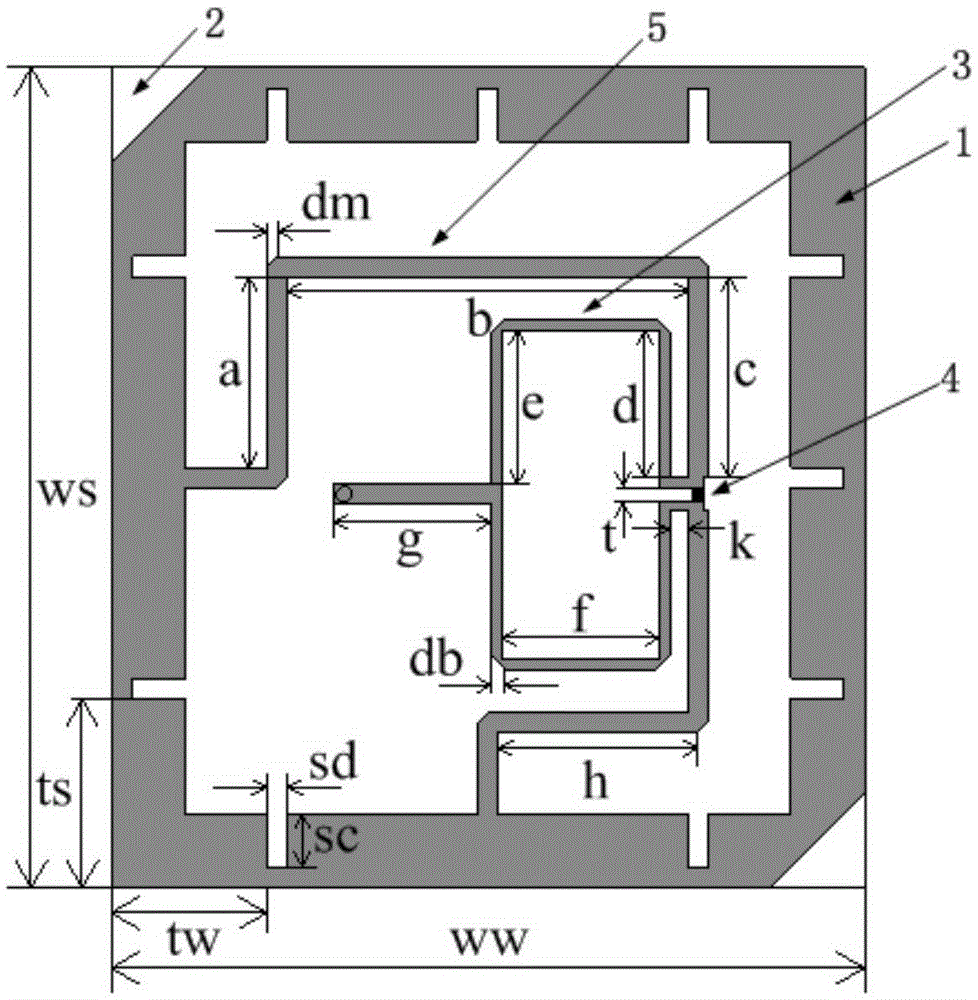
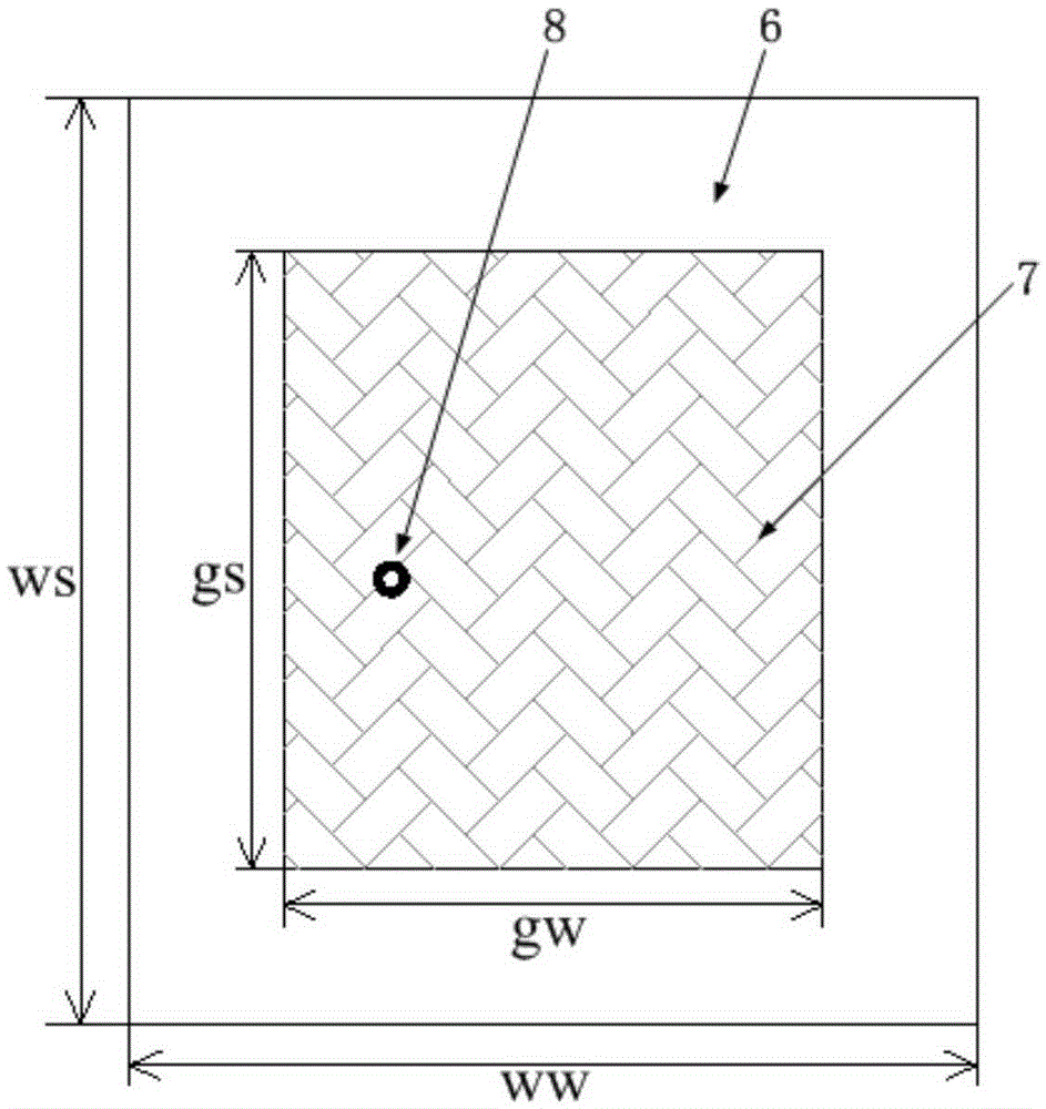
[0027] The RFID circularly polarized antenna is designed in the UHF frequency band with a center frequency of 915MHz, and the microstrip antenna structure is as follows: figure 1 , 2 As shown, it includes a dielectric substrate 6, a metal ground plate 7 disposed on the lower surface of the substrate, a square annular radiation patch 1 and a Wilkinson power divider 3 disposed on the upper surface of the substrate; the Wilkinson power divider 3 is located on the square annular radiation patch 1 Inside, its input terminal is the feed point 8, and the two output terminals on both sides of the resistor 4 are respectively connected to the midpoint of the two sides of the radiation patch through two sections of microstrip lines with different lengths.

[0028] Such as figure 1 As shown, the external dimensions of the radiation patch 1 are the long ...


PUM


Abstract

The invention discloses a novel RFID circularly polarized antenna, and belongs to the technical field of antennas. The antenna comprises a dielectric substrate, a metal ground plate, a square ring radiation patch and a Wilkinson power divider, wherein the metal ground plate is arranged on the lower surface of the substrate; and the square ring radiation patch is arranged on the upper surface of the substrate. The antenna disclosed by the invention is in a planar structure, and applicable to application in a plurality of environments; the radiation of the antenna is a bidirectional circularly-polarized radiation; and compared with a unidirectional radiation, the bidirectional circularly-polarized radiation has higher practicability on an RFID system and meets the requirements of the occasions, such as automatic fare collection systems for expressways and partial production lines, employing the RFID system.

Description

technical field [0001] The invention belongs to the technical field of antennas, and in particular relates to a novel RFID reader antenna applied to a highway automatic toll collection system. Background technique [0002] RFID is radio frequency identification technology. Radio frequency identification technology is an automatic identification technology that uses radio frequency to conduct non-contact two-way communication to achieve identification purposes and exchange data. Compared with traditional automatic identification systems (such as barcodes), RFID technology has many advantages: it can read or write data at a long distance, directional or non-directional, without keeping the identified target visible; it can read data through external materials; Work in harsh environments; handle multiple electronic tags at the same time; can store a large amount of information; can also physically locate objects through RFID tags, etc. [0003] The antenna of the radio frequen...

Claims


Application Information

Patent Timeline
Patent Type & Authority Applications(China)
IPC IPC(8): H01Q1/38H01Q1/50
Inventor 丁霄裴赢洲
Owner UNIV OF ELECTRONICS SCI & TECH OF CHINA
Why Eureka
Try Eureka