
Drive unit and electric power steering device including drive unit

A drive unit and component technology, applied in power steering mechanism, electric steering mechanism, electromechanical device, etc., can solve problems such as radio noise

Active Publication Date: 2016-02-10
DENSO CORP
View PDF7 Cites 19 Cited by
  • Summary
  • Abstract
  • Description
  • Claims
  • Application Information

AI Technical Summary

Problems solved by technology

Therefore, the noise leaked from the radiator and motor case of the motor is transmitted to the antenna of the radio equipment and transmitted to the communication device etc., which may cause radio noise

Method used


Image

  • Drive unit and electric power steering device including drive unit
  • Drive unit and electric power steering device including drive unit
  • Drive unit and electric power steering device including drive unit

Examples


no. 1 example

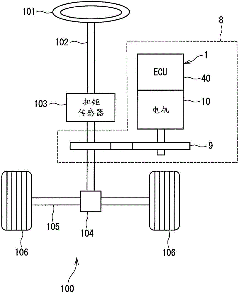
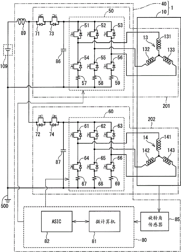
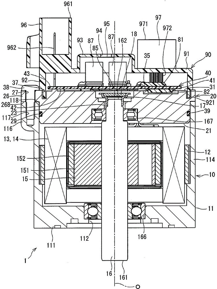
[0028] exist Figure 1 to Figure 12 The drive unit and the electric power steering apparatus in the first embodiment of the present disclosure are shown in . Hereinafter, in all the embodiments described below, for the sake of concise description, the same reference numerals represent the same components.

[0029] Such as figure 1 As shown, the drive unit 1 is applied to an electric power steering device 8 for assisting a steering operation by a driver. The drive unit 1 is an integral combination of a motor 10 serving as a rotating electric machine and an ECU 40 serving as a controller for controlling the motor 10 .

[0030] figure 1 A system diagram of a steering system 100 having an electric power steering device 8 is shown. The steering system 100 includes a steering wheel 101 , a column shaft 102 , a pinion 104 , a rack shaft 105 , wheels 106 , an electric power steering device 8 , and the like, each serving as components of the system.

[0031] A steering wheel 101 i...

no. 2 example

[0149] Figure 13 to Figure 16 A drive unit in a second embodiment of the present disclosure is shown. Figure 13 yes Figure 15 Sectional view of line XIII-XIII in.

[0150] With the drive unit 2 of the present embodiment, the motor 210 as a rotating electric machine and the ECU 40 as a controller are arranged integrally. The motor 210 has a motor housing 211 and a frame member 230 different from those in the above embodiments.

[0151] The motor case 211 has, for example, a bottom 220 and a cylindrical portion 214 , and has a bottom-closed cylindrical shape made of metal for heat conduction, such as aluminum. In the present embodiment, the bottom 220 faces the ECU 40 , and the other end or opposite side is the opening of the cylindrical portion 214 .

[0152] The fixing piece 216 for fixing the frame member 230 is arranged around the opening of the cylindrical portion 214, ie protrudes outward in the radial direction. In addition, a threaded hole 217 is drilled in the f...


PUM


Abstract

Provided are a drive unit and an electric power steering device including the drive unit. The drive unit that includes a rotating electric machine having a stator with winding wound on the stator and with a shaft rotating within the stator, and a rotor rotatable relative to the stator. The drive unit also includes a controller holding member disposed on one end of the rotating electric machine, and a controller having a substrate fixed to the controller holding member, a heat generation element mounted on a heat generation element mounting surface. The drive unit further includes a power supply connector connecting the substrate and a power supply, and a ground line coupled to a ground terminal of the power supply providing a conductive connection to the controller holding member via the substrate and the power supply connector. With this structure, the drive unit's common mode noise may be reduced.

Description

technical field [0001] The present disclosure generally relates to a drive unit and an electric power steering apparatus including the same. Background technique [0002] The conventional structure of electric motors used in vehicles is prone to noise, that is, the gap between the coils of the motor and the motor housing acts as a capacitor to generate noise. Such noise can be prevented by the following structure. For example, in the patent document Japanese Laid-Open Patent Publication H4-355602A (Patent Document 1), via a common mode path provided as a connection between the motor part and the vehicle body (that is, the motor case and the radiator are grounded to the vehicle body frame) to release the generated noise. [0003] In Patent Document 1, the noise affecting the controller is reduced by connecting the motor case and the radiator to the vehicle body frame, and as a tradeoff, the noise leaked from the motor increases. Furthermore, noise leaking from the motor's ...

Claims


Application Information

Patent Timeline
Patent Type & Authority Applications(China)
IPC IPC(8): H02K11/33H02K9/22B62D5/04
CPCH02K11/02H02K11/33B62D5/0406H02K9/227H02K9/223B62D5/0412B62D5/0463H02K5/225
Inventor 山崎雅志沢田武志
Owner DENSO CORP
Learn More