Swirl nozzle for treatment after exhaust of engine

A technology of exhaust post-treatment and swirling nozzles, which is applied in the direction of engine components, machines/engines, exhaust devices, etc., can solve the problems of NOx conversion efficiency decline, decline, exhaust pipe clogging and purification efficiency, etc., and achieve atomization quality Good, simplify the system structure and reduce the effect of installation

Active Publication Date: 2016-02-17
福爱电子(贵州)有限公司
View PDF5 Cites 4 Cited by
  • Summary
  • Abstract
  • Description
  • Claims
  • Application Information

AI Technical Summary

Problems solved by technology

In this case, but because the prior art forms droplets with larger particles in order to avoid the mutual interference between the multi-hole (typically four nozzle holes), the nozzle holes are often distributed along the circumferential direction, and the liquid does not After being fully atomized, it is directly sprayed on the wall of the exhaust pipe, and a part of the urea is easily crystallized and adhered to the exhaust pipe, resulting in blockage of the exhaust pipe or a decrease in purification efficiency.
On the other hand, the spraying of the porous beams is often uneven, resulting in poor mixing quality of urea and exhaust gas, and a decrease in the conversion efficiency of NOx

Method used


Image

  • Swirl nozzle for treatment after exhaust of engine
  • Swirl nozzle for treatment after exhaust of engine
  • Swirl nozzle for treatment after exhaust of engine

Examples


Embodiment Construction

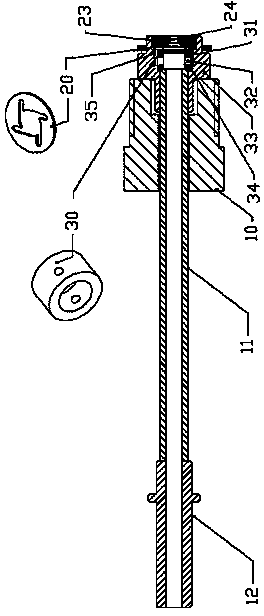
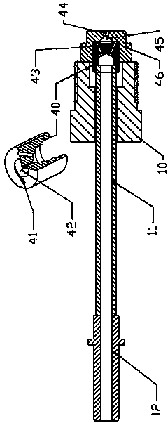
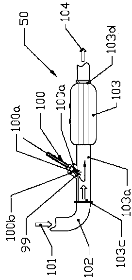
[0032] Such as figure 1Shown is a schematic structural diagram of the first embodiment of the swirl nozzle provided by the present invention, including swirl core 3, orifice plate 8, nozzle body 9, lock nut 10, heat insulating tube 11, quick connector 12 and so on. The swirl core 3 is a square cylinder as a whole, and one end face is provided with a swirl chamber 1 close to a cylindrical cavity and a tangential flow channel 2 tangential to the edge of the swirl chamber 1, while the other end face is provided with a connection center and Peripheral radial runners 15. The orifice plate 8 is a circular plate with a circular spray hole 5 in its center. One end of the heat insulating pipe 11 is inserted into the nozzle body 9 tightly, or is fixed integrally with the nozzle body 9 by means of welding, etc., and the other end is tightly connected with a quick connector 12 (by means of welding or pressing). The quick connector 12 meets the SAEJ2044 standard. The length of heat-insu...


PUM


Abstract

A swirl nozzle for treatment after exhaust of an engine comprises a nozzle body, a swirl chamber located in the nozzle body and a spraying hole located in the center of the swirl chamber, further comprises at least one tangential flow way, and is characterized in that the flow area of the tangential flow way is smaller than or equal to the flow area of the spraying hole. According to the nozzle, the nozzle is not prone to being blocked, reliable and stable in work, good in atomization quality, high in spraying precision, and more even in distribution of sprayed liquid, and is used for an SCR system and a DPF system.

Description

technical field [0001] The invention belongs to the technical field of engine exhaust aftertreatment, in particular to a liquid injection system for engine exhaust aftertreatment, including a NOx selective catalytic reduction (SCR) system and a particulate matter collector (DPF) regenerative fuel injection system. Background technique [0002] With the increasingly prominent environmental problems, energy saving and emission reduction has become an endless requirement for vehicles and engines. For this reason, various countries have issued a series of vehicle emission standards, which are becoming more and more stringent. In this regard, vehicles powered by internal combustion engines need to install exhaust after-treatment systems in order to meet emission requirements. For example, the SCR (Selective Catalytic Reduction) technology, which is mainly used for the catalytic treatment of pollutants such as NOx in the exhaust of diesel engines, has become a necessary technology...

Claims


Application Information

Patent Timeline
IPC IPC(8): F01N3/28F01N3/025
Inventor 郗大光张平杨延相
Owner 福爱电子(贵州)有限公司
Why Eureka
Try Eureka