

Sparse array broadband beamforming grating lobe suppressing method
A sparse array, grating lobe technology, applied in radio wave measurement systems, instruments, etc., can solve problems such as inapplicability to multi-target detection, and achieve the effect of low application cost and good practicability
- Summary
- Abstract
- Description
- Claims
- Application Information
AI Technical Summary
Problems solved by technology
Method used
Image

Examples
specific Embodiment approach 2
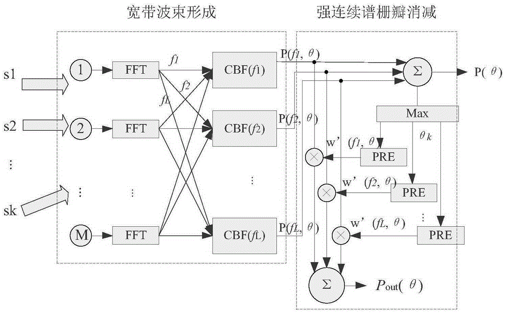
[0075] 2. Specific implementation mode two: the difference between this implementation mode and specific implementation mode one is: if Figure 4 As shown, firstly, FFT (Fast Fourier Transform) is performed on the received array signal to convert it into a frequency domain signal, and conventional beamforming is performed on each frequency point signal within the working frequency band bandwidth B of the frequency domain signal to obtain each The spatial spectrum output of the frequency point P(f i ,θ):
[0076] P(f i ,θ)=a(f i ,θ) H R(f i )a(f i ,θ)(12)
[0077] B is the signal frequency band, B=f h -f l , f l is the lower limit frequency of the working frequency band, f h is the upper limit frequency of the working frequency band, f i For FFT transformation, for the i-th frequency in signal frequency band B, i=1,2...L, L is the number of subbands corresponding to FFT in signal bandwidth B, L=B / Δf, B is signal bandwidth, Δf is FFT Frequency resolution when calcula...
specific Embodiment approach 3
[0088] 3. Specific implementation mode three: the difference between this implementation mode and specific implementation mode one or two is: the specific calculation method of the step 2 is as follows:
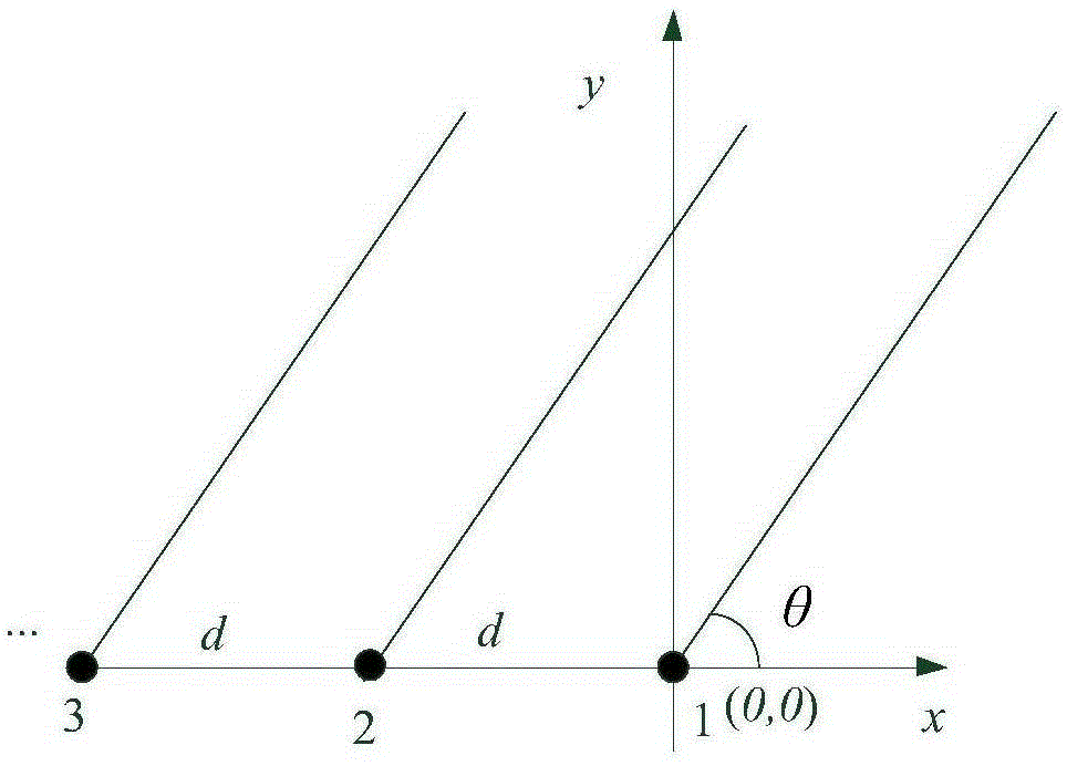
[0089] If the main lobe orientation is θ k , then the position where each frequency grating lobe appears The calculation formula is:
[0090] θ kfi =arcsin(sinθ k ±mλ i / d), m=1,2,...,0°kfi <180°(15)
[0091] Among them, m is the serial number corresponding to the grating lobe, which is a positive integer, and λ i =C / f i ,λ i for the frequency f i The corresponding wavelength, C is the speed of sound, d is the element spacing of the array, when m=0, the corresponding angle is the main maximum position, that is, the position of the target, and the angular position corresponding to the integer m in the range of other measurement areas is the grid Lobe position, there may be multiple grating lobes in the measurement area, the specific number is given by Under this co...
specific Embodiment approach 4
[0093] 4. Specific implementation mode four: the difference between this implementation mode and one of the specific implementation modes one to three is: the step 3 is specifically:
[0094] For the sound pressure array, the width of the grating lobe of the single-frequency signal is completely equal to the width of the main lobe. Therefore, the width of the grating lobe can be determined by the calculation formula of the width of the main lobe. For an equidistant linear array, the frequency is f i The zero-point main lobe width Δθ formed by the signal k (or zero-point beam width) corresponding to the calculation formula of the half-beam width is:
[0095] Δθ k =arcsin(λ i / Md)(16)
[0096] That is, sin(Δθ k )=λ i / Md, M is the number of array elements, grating lobe angle Then the formula for calculating the starting and ending range of the corresponding grating lobes is:
[0097]
[0098] grating lobe corresponds to the left range start point, grating lobe ...
PUM
 Abstract
Description
Claims
Application Information