Anti-parallel thyristor drive circuit for pulse width modulation voltage

A thyristor drive, thyristor technology, applied in electrical components, electronic switches, pulse technology and other directions, can solve the problem that the anti-parallel thyristor drive circuit cannot be applied to pulse width modulation voltage, etc., and achieves stable operation, novel circuit and small size.

Inactive Publication Date: 2016-02-17
BEIJING MECHANICAL EQUIP INST
View PDF4 Cites 2 Cited by
  • Summary
  • Abstract
  • Description
  • Claims
  • Application Information

AI Technical Summary

Problems solved by technology

[0003] The purpose of the present invention is to provide an anti-parallel thyristor drive circuit for pulse width modulation voltage, to solve the problem that the anti-parallel thyristor drive circuit cannot be applied to pulse width modulation voltage

Method used


Image

  • Anti-parallel thyristor drive circuit for pulse width modulation voltage
  • Anti-parallel thyristor drive circuit for pulse width modulation voltage

Examples


Embodiment Construction

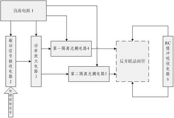
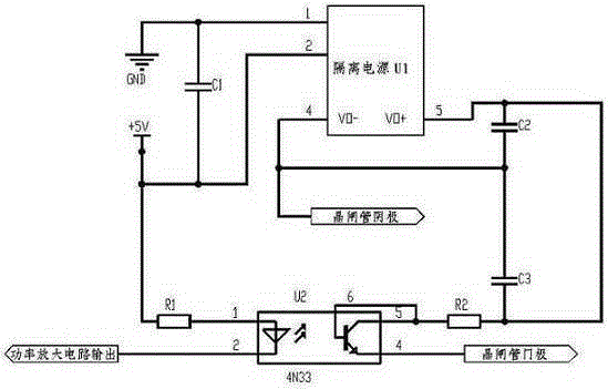
[0013] An anti-parallel thyristor drive circuit for pulse width modulation voltage, including: a DC power supply 1, a drive signal receiving circuit 2, a power amplifier circuit 3 and an RC buffer absorption circuit 6, and also includes: a first isolated optocoupler circuit 4 and a second Two isolated optocoupler circuits 5; the composition of the first isolated optocoupler circuit 4 and the second isolated optocoupler circuit 5 is exactly the same, both including: isolated power supply U1, optocoupler U2, resistor R1, resistor R2, capacitor C1, capacitor C2 and capacitor C3.

[0014] The DC positive output interface of the DC power supply 1 is respectively connected with the DC power positive input interface of the drive signal receiving circuit 2, the DC power positive input interface of the power amplifier circuit 3, the DC power positive input interface of the first isolated optocoupler circuit 4, and the second isolation The positive input interface of the DC power supply...


PUM


Abstract

The invention discloses an anti-parallel thyristor drive circuit for pulse width modulation voltage. The anti-parallel thyristor drive circuit comprises a direct current power supply (1), a drive signal receiving circuit (2), a power amplification circuit (3), an RC snubber circuit (6), a first isolating optically coupled circuit (4) and a second isolating optically coupled circuit (5), wherein the drive signal receiving circuit (2) reads a signal for controlling enabling of a thyristor from the outside when working; the power amplification circuit (3) is used for conveying a thyristor enable signal into high and low level signals with load-carrying capacity; the first isolating optically coupled circuit (4) and the second isolating optically coupled circuit (5) are each used for generating one path of isolated and completely synchronized thyristor drive signal, and providing required drive current to two thyristor gate input interfaces of an anti-parallel thyristor; and the RC snubber circuit (6) absorbs and restrains impulse overvoltage in the switch switching process. The anti-parallel thyristor drive circuit is novel in circuit, safe, reliable, small in size and stable in work.

Description

technical field [0001] The invention relates to an anti-parallel thyristor drive circuit, in particular to an anti-parallel thyristor drive circuit for pulse width modulation voltage. Background technique [0002] The anti-parallel thyristor circuit is an ideal fast AC switch. Its switch on and off is realized inside the circuit, and there are no problems such as arcing, contact wear and welding; the shutdown always occurs when the current crosses zero, and will not be caused by Transient high voltage caused by inductive energy storage in the load or line. The normal operation of the anti-parallel thyristor requires a stable and reliable drive circuit. The traditional thyristor drive circuit includes: DC power supply, drive signal receiving circuit, power amplifier circuit, RC buffer absorption circuit, isolation transformer and phase shift circuit. The sinusoidal AC voltage at both ends judges that the phase is zero-crossing, the driving signal is generated by the phase sh...

Claims


Application Information

Patent Timeline
Patent Type & Authority Applications(China)
IPC IPC(8): H02M1/08H03K17/08
CPCH02M1/083H03K17/08
Inventor 梁晓龙李艳明
Owner BEIJING MECHANICAL EQUIP INST
Why Eureka
Try Eureka