Automatic liquid draining and guiding device

A technology of automatic liquid discharge and liquid discharge port, applied in the field of medical devices, can solve the problems of endangering the safety of patients, electrification of drainage fluid, and inability to reduce the work pressure of nursing staff, etc., and achieve the effect of good safety, convenience and high precision.

Active Publication Date: 2016-02-24
孔令彬
View PDF6 Cites 8 Cited by
  • Summary
  • Abstract
  • Description
  • Claims
  • Application Information

AI Technical Summary

Problems solved by technology

The accuracy of mechanical automatic catheterization bag is not high
There are automatic urinary catheterization systems that use electronic methods, mostly based on hydraulic pressure and weight, but when the specific gravity of the patient's urine is different, there is a certain error in the conversion volume, and this type of product is used to solve the problem of monitoring the patient's bladder pressure and bladder function exercise. Mainly, it cannot solve the heavy, dirty and easily infected work of dumping urine and excrement in catheterization care, and cannot reduce the work pressure of nursing staff and reduce the risk of infection
[0004] At the same time, the electronic automatic catheterization system needs to place some electronic components in the drainage catheter. If the outer insulating layer is damaged, the drainage fluid is prone to electrification, which endangers the safety of the patient.
[0005] The electronic drainage valve of the current electronic catheterization products has no backup solution in case of power failure or other failures, which may easily lead to backflow of the drainage fluid, resulting in medical accidents
[0006] During the care of patients with major infectious diseases such as Ebola and plague, manual handling of patient urine and excrement will increase the risk of infection for nurses, so a high-safety product that can avoid direct contact is needed

Method used


Image

  • Automatic liquid draining and guiding device
  • Automatic liquid draining and guiding device
  • Automatic liquid draining and guiding device

Examples


Embodiment Construction

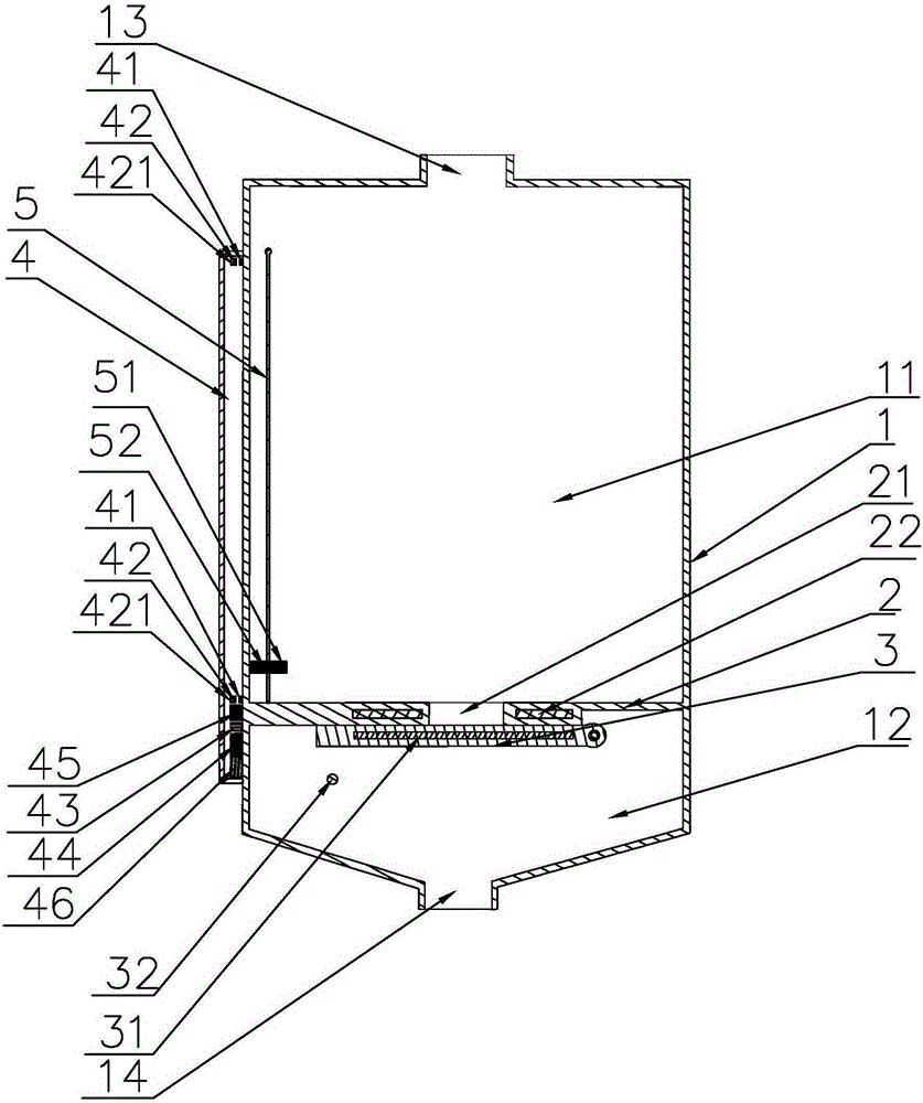
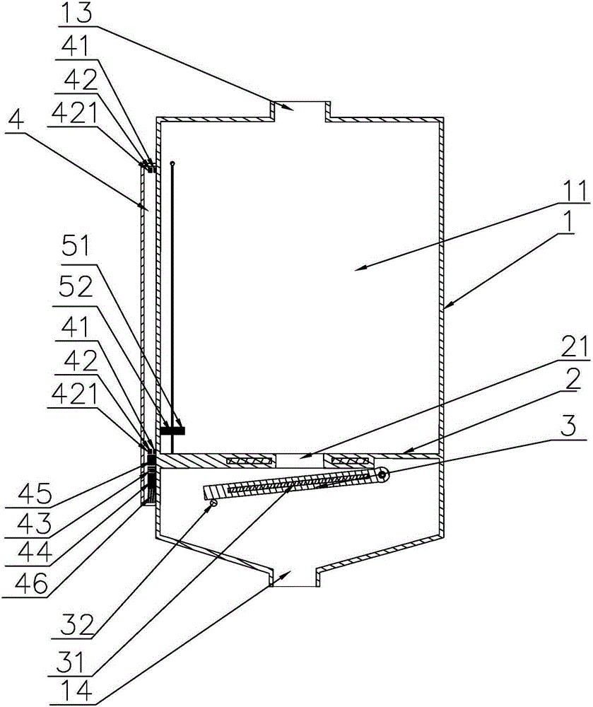
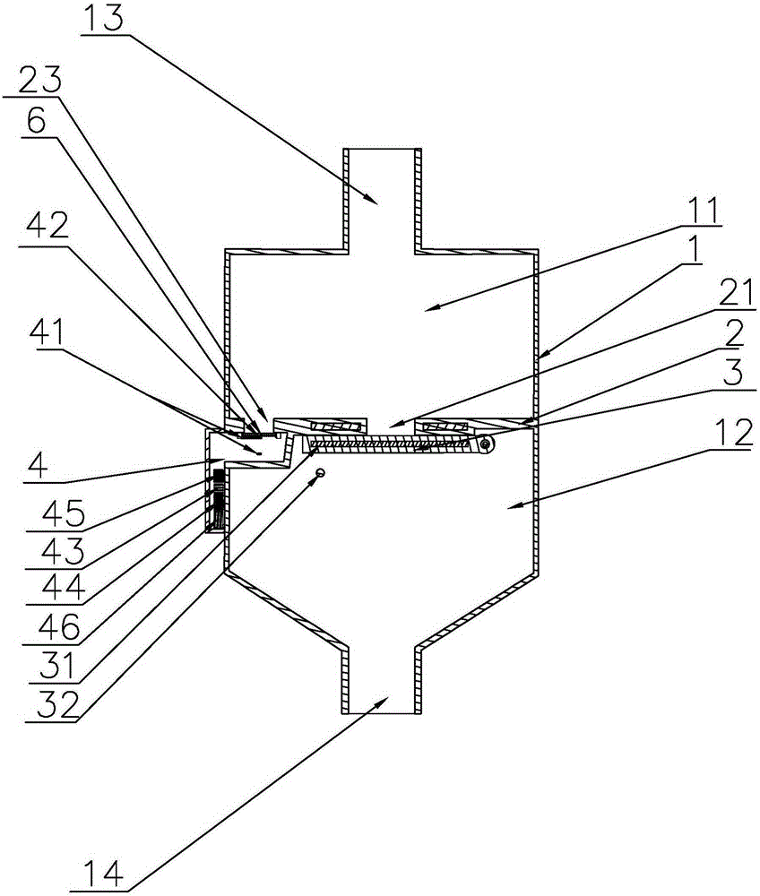
[0032] refer to Figure 1 to Figure 6 , the present invention is an automatic drainage device, comprising a drainage container 1 divided into a liquid storage chamber 11 located at the upper part and a liquid discharge channel 12 located at the lower part through a partition plate 2, the liquid storage chamber 11 is provided with a connecting pipe 13, The liquid discharge channel 12 is provided with a liquid discharge port 14, and the partition plate 2 is provided with a liquid discharge port 21 connecting the liquid storage chamber 11 and the liquid discharge channel 12, and a movable part that can seal the liquid discharge port 21 is also provided. Sealing gasket 3, and a control device equipped with a remote control receiving module that can forcibly control the movable sealing gasket 3 to open the liquid discharge port 21.

[0033] An automatic drainage and drainage device, comprising a drainage container 1 divided into a liquid storage chamber 11 at the upper part and a l...


PUM


Abstract

The invention discloses an automatic liquid draining and guiding device. The automatic liquid draining and guiding device comprises a liquid guiding container separated into a liquid storage cavity and a liquid drainage channel through a partitioning board, wherein the liquid storage cavity is provided with a connecting pipe, the liquid drainage channel is provided with a liquid drainage hole, the partitioning board is provided with a liquid draining hole communicating the liquid storage cavity and the liquid drainage channel, a movable sealing gasket capable of sealing the liquid drainage hole is arranged below the partitioning board, the device is further provided a control device capable of forcibly controlling the movable sealing gasket to open the liquid drainage hole and equipped with a remote control receiving module, or a control device capable of monitoring the liquid level inside the liquid storage cavity to open or close the liquid drainage hole through the movable sealing gasket. According to the device, the movement of the movable sealing gasket is controlled through the operation of remotely triggering the control device through a remote control contact module or the operation of monitoring the liquid level to start the control device, so that the opening and closing of the liquid drainage hole are indirectly controlled. The automatic liquid draining and guiding device is high in precision, the liquid drainage process does not need to be manually carried out, and the flow guiding condition can be accurately recorded, so that the labor intensity of the nursing personnel is effectively alleviated, the infection of an operator is avoided, and the automatic liquid draining and guiding device has better safety and convenience, and is applied to the field of medical apparatus and instruments.

Description

technical field [0001] The invention relates to the field of medical equipment, in particular to an automatic drainage device. Background technique [0002] In clinical nursing, the drainage device that stores the patient's drainage fluid usually requires the nursing staff to check and record the storage of the drainage fluid frequently and pour out the drainage fluid in time to prevent the drainage fluid from overflowing or backflowing back to the human body after the drainage fluid is full, causing iatrogenic pollution. [0003] Clinically, the fluid volume is basically used as the recording basis to deal with the drainage fluid. There is a situation that the accuracy of the mechanical automatic catheterization bag is not high. There are automatic urinary catheterization systems that use electronic methods, mostly based on hydraulic pressure and weight, but when the specific gravity of the patient's urine is different, there is a certain error in the conversion volume, an...

Claims


Application Information

Patent Timeline
Patent Type & Authority Applications(China)
IPC IPC(8): A61M1/00
CPCA61M1/69A61F5/44A61F5/4407A61F5/453A61F5/455A61M2202/0496A61M2205/3389A61M2205/502A61M1/70A61J1/2037A61M1/67A61M1/734
Inventor 胡绍勤
Owner 孔令彬
Why Eureka
Try Eureka