Converter gas blending device for hot blast stove

A technology of converter gas and hot blast stove, which is applied in the field of converter gas mixed combustion device, and can solve problems such as failure of injection function, poor pressure and flow stability, failure of mixed combustion function, etc.

Active Publication Date: 2018-02-02
LIANFENG STEEL (ZHANGJIAGANG) CO LTD
View PDF6 Cites 0 Cited by
  • Summary
  • Abstract
  • Description
  • Claims
  • Application Information

AI Technical Summary

Problems solved by technology

The above two converter gas blending devices have the following disadvantages: (1) Because the pressure junction of blast furnace gas and converter gas is often in fluctuations and the characteristics of the original pipe network, it is often necessary to greatly reduce the main branch of blast furnace gas Imported valves have certain safety hazards; (2) For the same reason, especially when the blast furnace gas pressure does not match the converter gas pressure, the injection function "fails" and "backflow" occurs, that is, the blast furnace gas backflows into the converter gas pipeline , which leads to the failure of the mixed firing function; (3) Due to the characteristics of the hot blast stove operation, the stove is replaced every hour. During the furnace replacement process, one hot blast stove stops firing within 12 to 15 minutes (take 3 hot blast stoves as an example , when the hot blast stove is replaced, the three hot blast stoves are changed from 2 burning and 1 delivery to 1 burning, 1 stop and 1 delivery), so it is necessary to frequently adjust the flow regulating valve in the main branch pipe of the converter gas, which will easily lead to the stability of the pressure and flow of the entire system poor sex

Method used


Image

  • Converter gas blending device for hot blast stove

Examples


Embodiment Construction

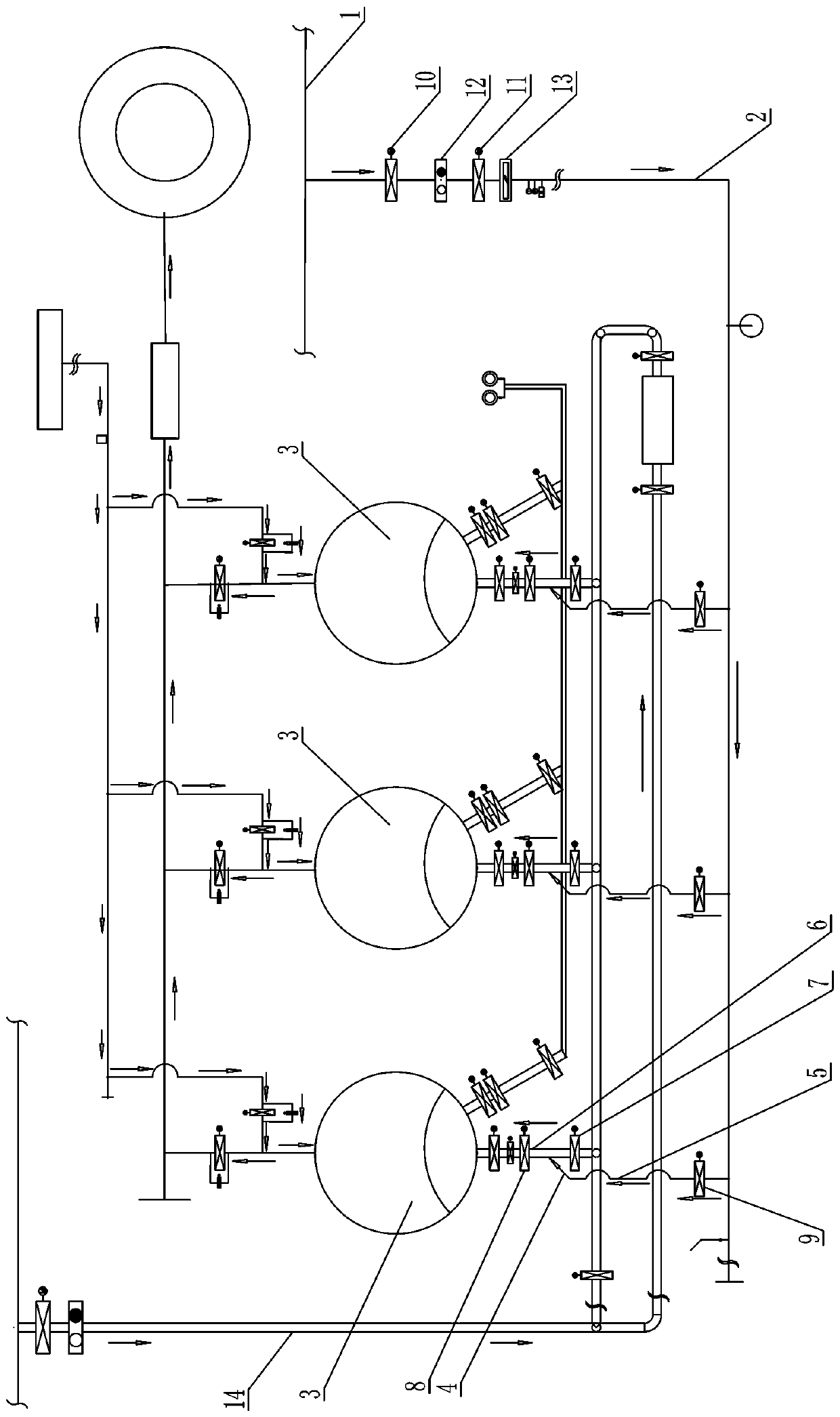
[0010] The present invention will be further described below in conjunction with the accompanying drawings and specific embodiments.

[0011] Such as figure 1 As shown, the described converter gas blending device for hot blast stoves includes: a converter gas main branch pipe 2 connected with the converter gas main pipe network 1, and the converter gas main branch pipe 2 corresponds to each hot blast stove 3 leading to a converter respectively Gas branch pipes 5, each converter gas branch pipe 5 communicates with the blast furnace gas branch pipe 6 corresponding to the hot blast stove 3 through an ejector pipe 3, each ejector pipe 4 is inserted into the corresponding blast furnace gas branch pipe 6, each ejector The insertion position of the pipe 4 is located between the blast furnace gas branch pipe flow regulating valve 7 on the corresponding blast furnace gas branch pipe 6 and the blast furnace gas branch pipe cut-off valve 8, and each converter gas branch pipe 5 is respect...


PUM


Abstract

The invention discloses a converter gas blending combustion device for hot blast furnaces. The converter gas blending combustion device comprises a converter gas main branch pipe connected with a converter gas main pipe network. A converter gas sub-branch pipe is led out of the converter gas main branch pipe corresponding to each hot blast furnace. Each converter gas sub-branch pipe is communicated with a blast furnace gas sub-branch pipe of the corresponding hot blast furnace through an ejection pipe. Each ejection pipe is inserted into the corresponding blast furnace gas sub-branch pipe. The insertion position of each ejection pipe is located between a blast furnace gas sub-branch pipe flow regulating valve and a blast furnace gas sub-branch pipe shut-off valve on the corresponding blast furnace gas sub-branch pipe. A converter gas sub-branch pipe flow regulating valve is arranged on each converter gas sub-branch pipe. The converter gas blending combustion device has the advantages that the phenomenon of backward flow of blast furnace gas can be effectively avoided; an inlet valve of a blast furnace gas main branch pipe does not need to be frequently and substantially turned down, a flow regulating valve on the converter gas main branch pipe does not need to be adjusted frequently, and the use safety is high.

Description

technical field [0001] The invention relates to a converter gas mixed burning device for a hot blast stove. Background technique [0002] The hot blast stove is one of the main supporting equipment of the blast furnace in the ironworks. The function of the hot blast stove is to continuously provide high-temperature hot air for the blast furnace. At present, for every 100°C increase in the air temperature of high-temperature hot air above 1000°C, the coke ratio can be saved by 15-20 kg / t, and every 100°C increase in the air temperature of high-temperature hot air below 1000°C can save 30 kg / t of coke ratio, so the increase Air temperature is an important measure for enterprises to save energy, reduce emissions, reduce costs and increase efficiency. [0003] Converter gas is a combustible gas with high calorific value produced in the process of converter steelmaking. The calorific value of a unit of converter gas is about 6000KJ, while the calorific value of a unit of blast f...

Claims


Application Information

Patent Timeline
Patent Type & Authority Patents(China)
IPC IPC(8): C21B9/10F27D17/00
CPCC21B9/10F27D17/00
Inventor 夏世桐张良斌曹兵黄裕东高国华
Owner LIANFENG STEEL (ZHANGJIAGANG) CO LTD
Why Eureka
Try Eureka