Oil field carbon dioxide injection huff-puff oil extraction ground device

A carbon dioxide and ground device technology, which is applied in the fields of mining fluid, earthwork drilling, sustainable manufacturing/processing, etc., can solve the problems of inability to recover pure carbon dioxide, achieve the effects of improving recovery rate, reducing working pressure and improving separation efficiency

Pending Publication Date: 2022-02-18
DESHI ENERGY TECH GRP CO LTD
View PDF0 Cites 0 Cited by
  • Summary
  • Abstract
  • Description
  • Claims
  • Application Information

AI Technical Summary

Problems solved by technology

[0005] In order to solve the above-mentioned problems in the prior art, that is, in order to solve the problem that the existing oilfield carbon dioxide injection huff and puff recovery technology cannot recover high-purity carbon dioxide, the present invention provides an oil field carbon dioxide injection huff and puff oil recovery surface device, including a carbon dioxide injection system, Oil production system and carbon dioxide recovery system

Method used


Image

  • Oil field carbon dioxide injection huff-puff oil extraction ground device
  • Oil field carbon dioxide injection huff-puff oil extraction ground device
  • Oil field carbon dioxide injection huff-puff oil extraction ground device

Examples


Embodiment 1

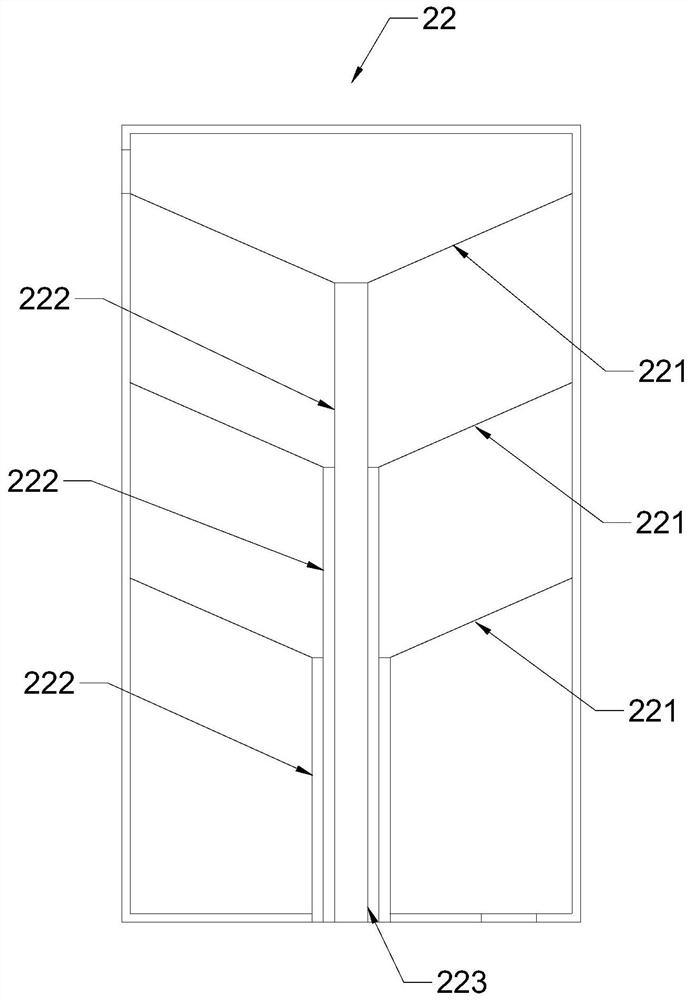
[0050] Embodiment 1: as figure 2 As shown, the filter screen 221 in the multi-stage slag removal tank 22 in this embodiment is set as a funnel shape with a low center and high surroundings. The slag removal tank 22 forms a slag discharge hole 223;

[0051] The slag discharge pipe 222 of each adjacent two layers of filter screens 221 is set in the form of step-by-step sleeves, and the slag discharge pipe 222 of the filter screen 221 near the inlet end of the multi-stage slag removal tank 22 is located on the inner side, away from the multi-stage slag removal tank 22 The slag discharge pipe 222 of the filter screen 221 at the inlet end is located on the outside.

[0052] By arranging the multi-stage slag removal tank 22 in the above-mentioned form, the multi-stage slag removal tank 22 can realize the filtering form of graded filtration, and the larger solid dross is blocked by the filter screen 221 near the inlet end of the multi-stage slag removal tank 22 , and the smaller s...

Embodiment 2

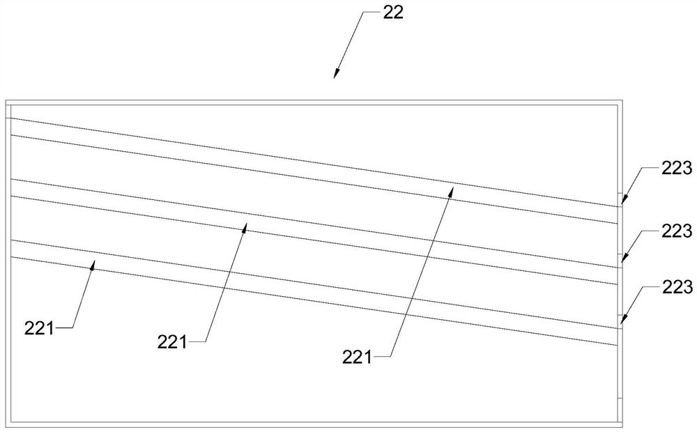
[0054] Embodiment 2: as image 3 with Figure 4 As shown, the filter screen 221 of the multi-stage slag removal tank 22 in this embodiment is set as a C-shaped curved plate in cross section, and the opening of the filter screen 221 faces upwards and goes from high to low inside the multi-stage slag removal tank 22 It is arranged obliquely, and several filter screens 221 are parallel to each other.

[0055] By setting the filter screen 221 in the form of a C-shaped curved plate, and making the openings of the multi-screen screens face to the upper side, the filter screen 221 can accept the crude oil flowing in from the inlet end of the multi-stage slag removal tank 22, and make the filtered The solid dregs that are filtered by the net 221 are collected at the bottom of the filter screen 221; by setting the filter screen 221 in a form that is inclined from high to low, the solid dregs that stay on the filter screen 221 can be removed under the action of their own gravity. The ...


PUM


Abstract

The invention provides an oil field carbon dioxide injection huff-puff oil extraction ground device. The device comprises a carbon dioxide injection system, an oil extraction system and a carbon dioxide recovery system, wherein the carbon dioxide injection system comprises a carbon dioxide storage tank and an injection pressure pump, one end of the injection pressure pump is communicated with the carbon dioxide storage tank, and the other end of the injection pressure pump is communicated with an oil extraction wellhead; the oil extraction system comprises an oil extraction pump, a multi-stage slag removal tank, a liquid-liquid separation tank and a gas-liquid separation tank, the multi-stage slag removal tank, the liquid-liquid separation tank and the gas-liquid separation tank are sequentially connected with the oil extraction pump, the liquid-liquid separation tank is communicated with a liquid carbon dioxide flow channel, and the gas-liquid separation tank is communicated with a gaseous carbon dioxide flow channel; the carbon dioxide recovery system comprises a gas impurity removal tank, an inlet end of the gas impurity removal tank is communicated with the liquid carbon dioxide flow channel and the gaseous carbon dioxide flow channel, an outlet end of the gas impurity removal tank is communicated with a compressor, and an outlet end of the compressor is communicated with the carbon dioxide storage tank. The device is advantaged in that pure carbon dioxide can be recycled, utilization efficiency of the carbon dioxide is improved, and generation of greenhouse gas is reduced.

Description

technical field [0001] The invention belongs to the technical field of oil production equipment, and specifically provides a carbon dioxide injection huff and puff oil production surface device in an oil field. Background technique [0002] Oilfield carbon dioxide injection huff and puff oil recovery technology refers to injecting a certain amount of carbon dioxide into the crude oil in the reservoir, and stuffing the well for a period of time, so that the crude oil and carbon dioxide are fully mixed, so that the volume of crude oil expands, the viscosity of crude oil is reduced, and the flow characteristics of crude oil are improved at the same time. It has a significant effect on reducing the water cut in the ultra-high water-cut stage of the late stage of production, and is one of the effective methods to increase the ultimate recovery of crude oil. [0003] However, the current CO2 injection huff and puff oil recovery technology in oilfields is usually directly discharge...

Claims


Application Information

Patent Timeline
Patent Type & Authority Applications(China)
IPC IPC(8): E21B43/34E21B43/16
CPCE21B43/34E21B43/35E21B43/164Y02P90/70
Inventor 崔仕章侯云福宋新旺王黎明张凤莲张荣军曾刚
Owner DESHI ENERGY TECH GRP CO LTD
Why Eureka
Try Eureka