Fuel jetting mixing device and low-pressure fuel jetting mixing method in supersonic velocity flow field

A technology of fuel injection and supersonic flow, which is applied in the field of low-pressure injection and mixing of fuel in supersonic flow field and fuel injection and mixing device in supersonic flow field, and can solve the problem of high injection pressure requirements, low penetration depth and poor mixing effect. and other problems, to achieve the effect of good mixing effect, increasing penetration depth and reducing working pressure

Active Publication Date: 2016-02-24
NAT UNIV OF DEFENSE TECH
View PDF4 Cites 8 Cited by
  • Summary
  • Abstract
  • Description
  • Claims
  • Application Information

AI Technical Summary

Problems solved by technology

[0004] The invention provides a fuel injection mixing device in a supersonic flow field and a fuel low-pressure injection mixing method to solve the problems of

Method used


Image

  • Fuel jetting mixing device and low-pressure fuel jetting mixing method in supersonic velocity flow field
  • Fuel jetting mixing device and low-pressure fuel jetting mixing method in supersonic velocity flow field
  • Fuel jetting mixing device and low-pressure fuel jetting mixing method in supersonic velocity flow field

Examples


Embodiment Construction

[0025] The embodiments of the present invention will be described in detail below with reference to the accompanying drawings, but the present invention can be implemented in various ways defined and covered.

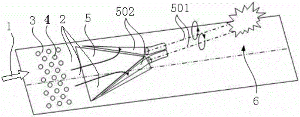
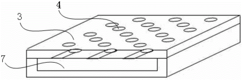
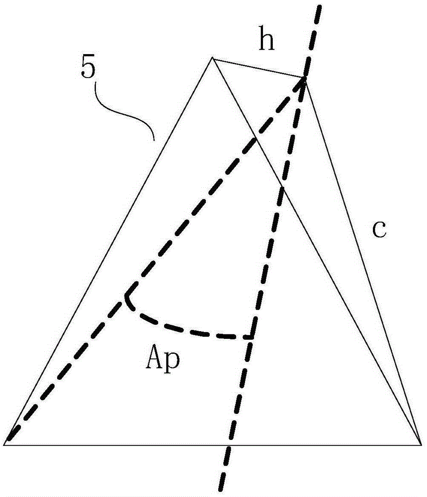
[0026] figure 1 It is a schematic diagram of the working principle of the fuel injection mixing device in the supersonic flow field of the preferred embodiment of the present invention; figure 2 yes figure 1 Schematic diagram of the structure of the fuel chamber and the injection hole; image 3 yes figure 1 Schematic diagram of the structure of the vortex generator in ; Figure 4 It is a schematic flow chart of a fuel low-pressure injection mixing method in a supersonic flow field according to a preferred embodiment of the present invention.

[0027] Such as figure 1As shown, the fuel injection and mixing device in the supersonic flow field of this embodiment includes: a fuel supply system for injecting gaseous fuel 2 into the high-speed main flow 6 in the superso...


PUM


Abstract

The invention discloses a fuel jetting mixing device and a low-pressure fuel jetting mixing method. The fuel jetting mixing device in a supersonic velocity flow field comprises a fuel supply system, mini-type tangential spraying holes and a vortex generator. The supersonic velocity is injected into gas-state fuel supplied by the fuel supply system through the mini-type tangential holes, the gas-state fuel flows to be close to the bottom of a wall face boundary layer and driven by upper high-speed airflow of the boundary layer to flow to the vortex generator, and an inverse spiral flow direction vortex pair wrapping the fuel is formed through high-speed airflow and in the disengaging process of the gas-state fuel on the side edge of the vortex generator; the inverse spiral flow direction vortex pair gradually ascends to get away from the wall face to enter the high-speed main flow through a self-induction mechanism of a vortex structure of the inverse spiral flow direction vortex pair; by means of the instable factor of the inverse spiral flow direction vortex pair in the high-speed main flow, the inverse spiral flow direction vortex pair is controlled to be broken in the high-speed main flow, the gas-state fuel wrapped by the inverse spiral flow direction vortex pair is rapidly mixed with the high-speed main flow, and the purpose of jetting mixing is achieved. The jetting power comes from the kinetic energy inherited by the inverse spiral flow direction vortex pair from the high-speed incoming flow while not relaying on high-pressure driving.

Description

technical field [0001] The invention relates to the technical field of fuel injection, in particular to a fuel injection mixing device in a supersonic flow field. In addition, the present invention also relates to a low-pressure fuel injection and mixing method in a supersonic flow field comprising the fuel injection and mixing device in a supersonic flow field. Background technique [0002] A scramjet is a ramjet in which fuel burns in a supersonic airflow, where fuel injection and mixing are one of the key technologies in scramjet design. The penetration height of the jet and its downstream mixing efficiency are important indicators for evaluating the fuel injection scheme, which will directly affect the ignition and combustion efficiency of the engine, and also have a profound impact on the working process and overall performance of the entire engine. Especially in large-sized engine combustion chambers, in order to ensure sufficient contact and mixing of the fuel and th...

Claims


Application Information

Patent Timeline
IPC IPC(8): F02K7/14
CPCF02K7/14F05D2260/60
Inventor 刘卫东王博孙明波
Owner NAT UNIV OF DEFENSE TECH
Why Eureka
Try Eureka