Electro-hydraulic compound servo control system

A servo control system and electro-hydraulic composite technology, applied in servo motor components, fluid pressure actuation system components, fluid pressure actuation devices, etc., can solve problems such as wasting energy, poor anti-pollution ability, and reducing system work efficiency. Achieve the effects of improving work efficiency, strong anti-pollution ability, and reducing system weight

Active Publication Date: 2017-10-24
SHANGHAI XINYUE METER FACTORY
View PDF5 Cites 0 Cited by
  • Summary
  • Abstract
  • Description
  • Claims
  • Application Information

AI Technical Summary

Problems solved by technology

In the traditional electro-hydraulic servo control position system, the electro-hydraulic servo valve adopts the double nozzle baffle type electro-hydraulic servo valve, and its inlet must maintain the rated working pressure, otherwise it will affect the dynamic characteristics of the system and the position control accuracy, the double nozzle baffle type The structure has poor anti-pollution ability, large leakage and easy damage, which greatly reduces the reliability and energy-saving efficiency of the system
The constant working pressure at the inlet is guaranteed by the hydraulic oil source in the mode of quantitative pump and relief valve, which cannot change with the load, which wastes a lot of energy and greatly reduces the working efficiency of the system

Method used


Image

  • Electro-hydraulic compound servo control system

Examples


Embodiment Construction

[0042] The present invention will be described in detail below in conjunction with specific embodiments. The following examples will help those skilled in the art to further understand the present invention, but do not limit the present invention in any form. It should be noted that those skilled in the art can make several modifications and improvements without departing from the concept of the present invention. These all belong to the protection scope of the present invention.

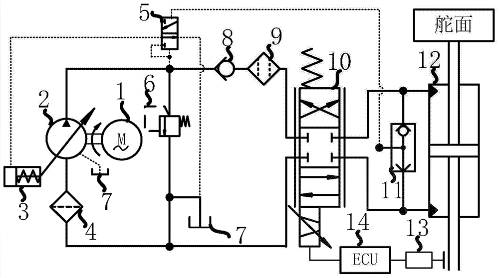
[0043] In this example, if figure 1 As shown, the electro-hydraulic compound servo control system provided by the present invention includes an intermediate frequency motor 1, a coarse filter 4, an overflow valve 6, an oil tank 7, a one-way valve 8, a hydraulic cylinder 12, a position sensor 13 and a controller 14, and its characteristics It also includes: a load sensing pump, an electro-hydraulic servo valve 10 and a shuttle valve 11;

[0044] The load sensing pump includes a variable displaceme...


PUM


Abstract

The invention provides a novel compound electro-hydraulic servo control system which comprises an intermediate frequency motor, an oil tank, a hydraulic cylinder, a load sensing pump, an electro-hydraulic servo valve and a shuttle valve, wherein the intermediate frequency motor is used for driving the load sensing pump; the outlet of the load sensing pump is communicated with the oil inlet of the electro-hydraulic servo valve, and the oil inlet is communicated with the outlet of the oil tank; the oil returning opening of the electro-hydraulic servo valve is communicated with the inlet of the oil tank, and the first control opening and the second control opening of the electro-hydraulic servo valve are respectively communicated with the first chamber and the second chamber of the hydraulic cylinder; the first comparing input opening and the second comparing input opening of the shuttle valve are respectively communicated with the first chamber and the second chamber of the hydraulic cylinder; the pressure signal output opening of the shuttle valve is connected with the load sensing chamber of a pressure compensator on the load sensing pump; the inlet of the pressure compensator is communicated with the outlet of the load sensing pump, the control opening of the pressure compensator is communicated with the variable displacement mechanism of the load sensing pump, and the oil returning opening of the pressure compensator is communicated with the oil tank. According to the novel compound electro-hydraulic servo control system, the outlet working pressure of the load sensing pump can be changed along with the size of load, and the purpose of energy saving is achieved.

Description

technical field [0001] The invention relates to a hydraulic servo control system, in particular to an electro-hydraulic composite servo control system. Background technique [0002] The electro-hydraulic servo control position system is the most important and widely used branch of the hydraulic servo control system. It means that the electro-hydraulic servo valve receives electrical signals from the controller to control the flow into the hydraulic cylinder, so as to achieve the purpose of precisely controlling the position of the piston rod. In the traditional electro-hydraulic servo control position system, the electro-hydraulic servo valve adopts the double nozzle baffle type electro-hydraulic servo valve, and its inlet must maintain the rated working pressure, otherwise it will affect the dynamic characteristics of the system and the position control accuracy, the double nozzle baffle type The structure has poor anti-pollution ability, large leakage and easy damage, whic...

Claims


Application Information

Patent Timeline
Patent Type & Authority Patents(China)
IPC IPC(8): F15B13/044F15B13/16F15B21/08
CPCF15B13/044F15B13/16F15B21/08F15B2013/0448
Inventor 张仲良傅俊勇朱康武张鑫彬
Owner SHANGHAI XINYUE METER FACTORY
Why Eureka
Try Eureka