Electric-hydraulic proportional load-sensitive pump and pump valve joint control servo system

A load-sensing pump and electro-hydraulic proportional technology, applied in servo motor components, fluid pressure actuation system components, pumps, etc., can solve the problems of limited output force of electromagnetic proportional valves, affecting response speed, large force, etc., to achieve Fast response to differential pressure adjustment, improved dynamic response, and improved work efficiency

Active Publication Date: 2019-03-08
SHANGHAI AEROSPACE CONTROL TECH INST
View PDF9 Cites 0 Cited by
  • Summary
  • Abstract
  • Description
  • Claims
  • Application Information

AI Technical Summary

Problems solved by technology

[0003] At present, the load sensing pump has two modes of manual and electric control. Among them, for the manual load sensing pump, the outlet pressure P is manually adjusted. S and load pressure P L The pressure difference value can not realize the remote automatic adjustment of the pressure difference value
When the initial pressure difference is adjusted to a large value, the purpose of energy saving cannot be achieved; when the initial pressure difference is adjusted to the minimum, although the system work efficiency can be improved, but the dynamic response speed of the load sensitive pump is slow, resulting in Less than the purpose of the dynamic frequency response of the valve control servo system
[0004] For the electronically controlled load-sensing pump, the pressure sensor is used to collect the load signal, and the controller directly drives the electromagnetic proportional valve output force to compare with the outlet pressure of the load-sensing pump to form a constant pressure difference. It can also be adjusted, but the outlet pressure of the load-sensitive pump is relatively large, and the force is also large, while the output force of the electromagnetic proportional valve is limited, which cannot form a good acceleration performance, thereby affecting the response speed of adjusting the constant pressure difference value, that is, affecting the load-sensitive Dynamic Response of the Pump

Method used


Image

  • Electric-hydraulic proportional load-sensitive pump and pump valve joint control servo system
  • Electric-hydraulic proportional load-sensitive pump and pump valve joint control servo system

Examples


Embodiment Construction

[0024] The present invention will be further elaborated below by describing a preferred specific embodiment in detail in conjunction with the accompanying drawings.

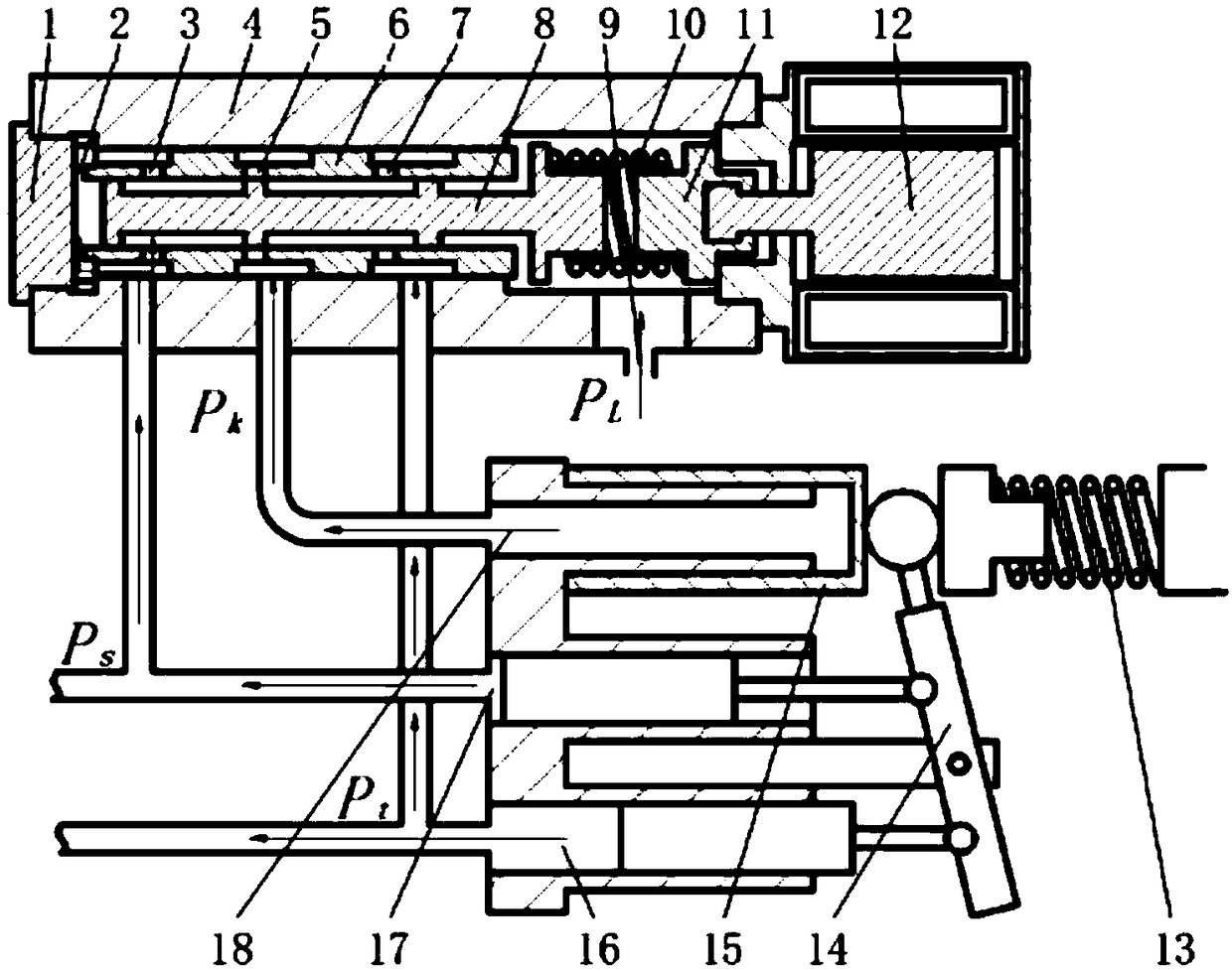
[0025] Such as figure 1 As shown, an electro-hydraulic proportional load sensitive pump provided in this embodiment includes: a plug 1, a housing 4, a valve sleeve 6, a valve core 8, a pressure regulating spring 10, a push rod 11, a proportional electromagnet 12, a return Spring 13, swash plate 14 and control piston 15; the valve sleeve 6 is located inside the housing 4, close to the first end of the housing, and is in interference fit with the inner wall of the housing 4, and the valve core 8 is located inside the valve sleeve 6; the pressure regulating spring 10 and the push rod 11 are sequentially arranged inside the housing 4, close to the second end of the housing 4, and the pressure regulating spring 10 is located in the between the spool 8 and the push rod 11; the proportional electromagnet 12 is arranged...


PUM


Abstract

The invention discloses an electric-hydraulic proportional load-sensitive pump and a pump valve joint control servo system. The electric-hydraulic proportional load-sensitive pump mainly comprises anend cap, a shell, a valve bush, a valve element, a pressure adjusting spring, a push rod, a proportion electro-magnet, a reset spring, a swash plate and a control piston. The work pressure PS of an outlet of the load-sensitive pump keeps constant differential pressure changes along with a load PL, the constant differential pressure can be adjusted through the proportion electro-magnet, the differential pressure adjusting response is fast, and the dynamic response speed of the electric-hydraulic proportional load-sensitive pump can be greatly increased. The pump valve joint control servo systemis free of overflow loss, and the work efficiency of the pump valve joint control servo system can be greatly improved while the high-frequency dynamic characteristic is met.

Description

technical field [0001] The invention relates to the field of hydraulic servo control systems, in particular to an electro-hydraulic proportional load sensitive pump and a pump valve joint control servo system. Background technique [0002] The pump-valve joint control servo system is an important branch of power transmission. It can fully combine the advantages of both the pump control servo system and the valve control servo system, and abandon the corresponding shortcomings. It is an ideal electro-hydraulic servo system. Therefore It is also a hotspot and focus of research by international experts. [0003] At present, the load sensing pump has two modes of manual and electric control. Among them, for the manual load sensing pump, the outlet pressure P is manually adjusted. S and load pressure P L It is impossible to realize the remote automatic adjustment of the pressure difference. When the initial pressure difference is adjusted to a large value, the purpose of energ...

Claims


Application Information

Patent Timeline
Patent Type & Authority Applications(China)
IPC IPC(8): F15B13/02F15B13/044F15B21/08F15B21/041F04B1/12
CPCF04B1/122F15B13/02F15B21/041F15B21/08F15B2013/0448
Inventor 张仲良方沁林张鑫彬李勇滕斌峰
Owner SHANGHAI AEROSPACE CONTROL TECH INST
Why Eureka
Try Eureka