
Test method for fatigue crack growth rate of steel box girder

A technology of fatigue crack growth and rate testing, which is applied in the direction of applying stable tension/pressure to test the strength of materials, etc., can solve the problems that the physical structure is far apart, cannot be dynamically collected in real time, and is difficult to obtain, so as to save the stoppage test Time to measure crack length, avoid crack tip plastic passivation, real and reliable effect of growth rate

Active Publication Date: 2018-01-02
武汉钢铁有限公司
View PDF7 Cites 0 Cited by
  • Summary
  • Abstract
  • Description
  • Claims
  • Application Information

AI Technical Summary

Problems solved by technology

The current national standard GB / T 6398-2000 stipulates the test method for the fatigue crack growth rate of metal materials, but the object of the material test is a standard sample, and the constraints it receives are far from those of the solid structure. How to apply the results of the fatigue crack growth rate test to the solid steel box girder structure remains to be further studied
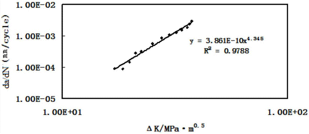
[0003] However, there are three major difficulties in the fatigue crack growth rate test of the solid steel box girder: 1) the physical size of the steel box girder is too large, and the load required for the test often exceeds the load capacity of the existing testing machine; 2) the solid structure of the steel box girder Complicated, the crack length is a variable during crack growth, and real-time dynamic acquisition is not possible; 3) The geometric solution of the stress intensity factor K of the steel box girder structure is difficult to obtain, which directly affects the solution of ΔK in the fatigue crack growth rate Paris formula

Method used


Image

  • Test method for fatigue crack growth rate of steel box girder
  • Test method for fatigue crack growth rate of steel box girder
  • Test method for fatigue crack growth rate of steel box girder

Examples


Embodiment Construction

[0035] The present invention will be further described in detail below in conjunction with the accompanying drawings and specific embodiments.

[0036] The test method for fatigue crack growth rate of steel box girder includes the following steps:

[0037] A. Preparation of steel box girder structural member samples

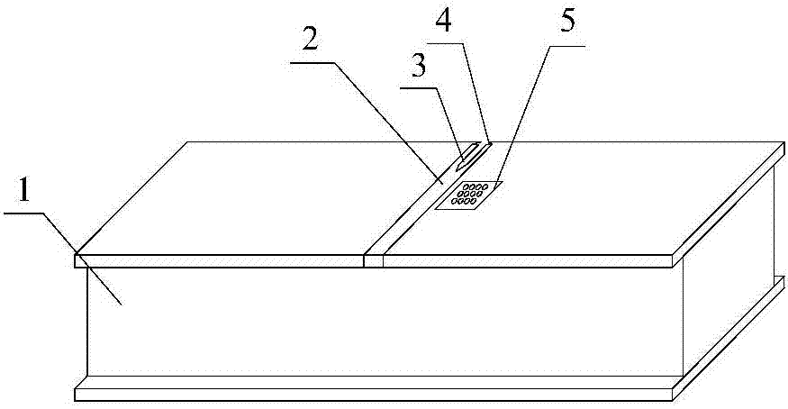
[0038] a1) According to the actual size of the steel box girder to be tested, the steel box girder sample is reduced in proportion according to the composition of the physical structure of the steel box girder to be tested and the welding process. The actual size and structure of the box girder are consistent, and the constraint state around it after the crack is formed is consistent with the actual steel box girder under test;

[0039] a2) Determine the dangerous section prone to crack propagation on the steel box girder sample according to the stress characteristics of the measured steel box girder physical structure, and process the mechanical notch on the da...


PUM


Abstract

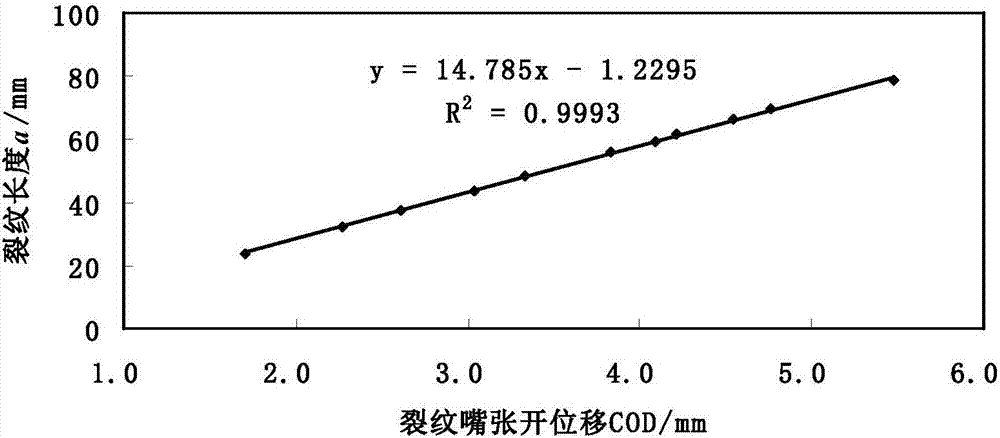
The invention discloses a fatigue crack propagation rate testing method of a steel box girder. The fatigue crack propagation rate obtained by structure solid tests of the method is truer and more reliable than that obtained by the Paris equation obtained by present material tests for fatigue crack propagation. The Paris equation of the method is more instructive when being used for predicating residual life in a service period of a structure. When being used for measuring crack lengths, the method is different from conventional methods that shut down and measure with a vernier caliper. According to the method, a COD clip gauge is mounted to the front end of a mechanical gap of a steel box girder test piece, the linear relation between the COD clip gauge and the crack length a measured by the vernier caliper is calibrated through static load tests, the linear relation is applied to dynamic tests for the fatigue crack propagation rate and the real crack length a is measured directly through reading of the COD clip gauge, and therefore influences on accuracy of fatigue test results, which are caused by crack-tip plastic blunting caused by middle shutdown in dynamic fatigue tests, are avoided, time of shutting down tests and testing crack lengths is saved, and the test efficiency is increased.

Description

technical field [0001] The invention belongs to the field of testing the mechanical properties of metal materials, in particular to a method for testing the fatigue crack growth rate of steel box girders. Background technique [0002] Steel box girders are widely used in the construction of lifting equipment, large bridges and steel structure houses. This kind of structural parts is subjected to various short-term periodic cyclic loads during service, and is prone to fatigue failure after long-term use, resulting in fracture and collapse of the structure, which is very dangerous. Therefore, it is often necessary to carry out safety assessment of steel box girder structural parts in engineering design, and it is necessary to continuously monitor its surface crack growth and estimate the remaining life of the structure during service. Fatigue crack growth rate test is a test to evaluate the speed of fatigue crack growth of defective components, which can effectively evaluate ...

Claims


Application Information

Patent Timeline
Patent Type & Authority Patents(China)
IPC IPC(8): G01N3/08
CPCG01N3/08
Inventor 刘冬薛欢余立陈士华宋育来吴立新杜丽影彭文杰
Owner 武汉钢铁有限公司
Learn More