[0035] The technical solutions of the present invention will be clearly and completely described below in conjunction with the accompanying drawings. Apparently, the described embodiments are some of the embodiments of the present invention, but not all of them. Based on the embodiments of the present invention, all other embodiments obtained by persons of ordinary skill in the art without making creative efforts belong to the protection scope of the present invention.
[0036] In the description of the present invention, it should be noted that the terms "center", "upper", "lower", "left", "right", "vertical", "horizontal", "inner", "outer" etc. The indicated orientation or positional relationship is based on the orientation or positional relationship shown in the drawings, and is only for the convenience of describing the present invention and simplifying the description, rather than indicating or implying that the referred device or element must have a specific orientation, or in a specific orientation. construction and operation, therefore, should not be construed as limiting the invention. In addition, the terms "first", "second", and "third" are used for descriptive purposes only, and should not be construed as indicating or implying relative importance. Wherein, the terms "first position" and "second position" are two different positions.
[0037] In the description of the present invention, it should be noted that unless otherwise specified and limited, the terms "installation", "connection" and "connection" should be understood in a broad sense, for example, it can be a fixed connection or a detachable connection. Connected, or integrally connected; it can be mechanically connected or electrically connected; it can be directly connected or indirectly connected through an intermediary, and it can be the internal communication of two components. Those of ordinary skill in the art can understand the specific meanings of the above terms in the present invention in specific situations.
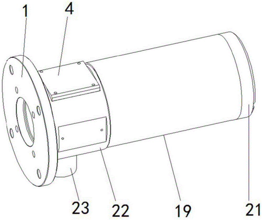
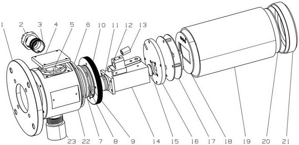
[0038] figure 1 A schematic diagram of the overall structure of an online dust measuring instrument using the light scattering method provided by an embodiment of the present invention; figure 2 An exploded view of an online dust measuring instrument using a light scattering method provided for an embodiment of the present invention.
[0039] The invention provides an online dust measuring instrument using light scattering method, such as figure 1 and figure 2 As shown, the online dust measuring instrument using the light scattering method includes: a housing 19, a laser light source 13, a filter 15 and a source circuit board 17, the housing 19 is provided with a first optical channel, and the filter The sheet 15 and the receiving source circuit board 17 are arranged in the first optical channel, and arranged in sequence along the extension direction of the first optical channel, and the laser light source 13 is used to emit a laser with a predetermined wavelength into the smoke to be measured The light scattered by the flue gas to be measured includes laser light of a predetermined wavelength and interference light, and the receiving source circuit board 17 is used to receive the laser light of a predetermined wavelength scattered by the smoke gas to be measured and process the laser light of a predetermined wavelength. The source circuit board 17 is electrically connected with the power supply communication plug.
[0040] The laser light source 13 is arranged in the housing 19, and can emit laser light of a predetermined wavelength into the flue gas to be measured through the shell. The optical filter 15 is selected according to the wavelength of the laser light emitted by the laser light source 13, allowing the laser light of the predetermined wavelength to be measured. The laser light scattered by the smoke passes through, and the light scattered by the smoke, such as other natural light, will be absorbed by the optical filter 15 and thus cannot be received by the receiver circuit board 17 .
[0041] Among them, the laser light source 13 has the following characteristics: 1. good monochromaticity: the color of the laser is very pure, and its monochromaticity is more than 10 times higher than that of ordinary light sources; 2. strong directionality: the divergence solid angle of the laser beam is very small, which is Milliradian scale, 2-3 orders of magnitude smaller than the divergence angle of ordinary light or microwave; ③High brightness: the radiance at the laser focus is 10-100 times higher than that of ordinary light. Therefore, the present invention uses laser light as a light source to obtain monochromatic emitted light, eliminate interference from natural factors, and improve measurement accuracy.
[0042]Wherein, the optical filter 15 is made by adding special dyes to plastic or glass sheets, and the red optical filter 15 can only allow red light to pass through, and so on. The transmittance of the glass sheet is almost the same as that of air, and all colored light can pass through, so it is transparent, but after being dyed with a dye, the molecular structure changes, and the refractive index also changes, which changes the passage of some colored light. Such as a bundle of white light passes through the blue filter 15, what emits is a bundle of blue light, while green light and red light are very few, and most of them are absorbed by the filter 15. The optical filter 15 is selected according to the properties of the laser light emitted by the laser light source 13 to ensure that the optical filter 15 absorbs all light except the laser light emitted by the laser light source 13 .
[0043] The dust measuring instrument provided by the present invention uses the light scattering method to measure the dust concentration. When measuring, one end of the casing 19 is closed, and the other end of the casing 19 communicates with the area to be measured, and then the laser light source 13 is turned on so that the laser light source 13 passes through the casing 19 Laser light with a predetermined wavelength is emitted into the flue gas to be measured. Natural light such as sunlight, refracted light, and laser light with a predetermined wavelength are scattered by the flue gas and enter the housing 19. The optical filter 15 can filter the scattered light to remove sunlight, natural light such as refracted light, the light scattered by the flue gas to be measured includes laser light of a predetermined wavelength and interfering light, and the filter is used to filter out the interfering light, allowing the scattered light of the laser light of a predetermined wavelength emitted by the laser light source 13 to pass through, In this way, the light received by the receiving source circuit board 17 is laser light of a predetermined wavelength scattered by the smoke. Under the condition of certain optical system and dust properties, the scattered light intensity is proportional to the dust concentration, so the receiving source circuit board 17 The final laser intensity is used to calculate the dust concentration. The invention eliminates the influence of interference factors in the natural environment on the measurement results, and improves the accuracy and reliability of the measurement results. The invention is widely applicable to the online continuous monitoring of the concentration of dust particles in the smoke discharge system, especially for the uninterrupted monitoring of the smoke discharge system with harsh natural environment and large interference of monitoring factors.
[0044] The dust particle on-line monitor provided by the invention adopts the principle of light scattering method for measurement, and only needs to be installed on one side of the flue gas discharge chimney for monitoring. In the source, the measurement result can be obtained immediately by receiving the source circuit board 17 for analysis and calculation, which is simple, fast and efficient. In addition, measurements are performed using optical methods, there are no mechanical wear parts, and the lifetime is high.
[0045] Further, the receiving source circuit board 17 includes a light source receiving module, a display screen 20 module and a signal output module connected in sequence, and the light source receiving module receives and processes the laser light scattered by the flue gas to be measured, and the display screen 20 module It is used for displaying the processing result of the light source receiving module and outputting the processing result through the signal output module.
[0046] Among them, the light source receiving module receives the laser light scattered by the flue gas and performs photoelectric conversion processing, converts the light intensity information of the laser light into the concentration information of dust, and sends the information of the electrical signal to the display screen 20 module, and the display screen 20 module can display The dust concentration information is output to the user through the signal output module.
[0047] Preferably, a display screen 20 is also provided in the casing 19 for conveniently observing the information of the dust concentration.
[0048] In addition, the signal output module can be connected with an online dust monitoring system, and the signal output module transmits the dust concentration information to the dust online monitoring system in real time, so as to obtain the dust concentration information in real time.
[0049] Further, the source receiving circuit board 17 also includes a light source generating module connected to the laser light source 13 for driving the laser light source 13 to emit laser light. When receiving power from the source circuit board 17, the light source generating module drives the laser light source 13 to emit light.
[0050] In addition, the dust measuring instrument can also include a power supply communication plug, which can be connected with a power supply and a communication system, the power supply communication plug is connected to the receiving source circuit board through a line, and the receiving source circuit board is powered by the power supply communication plug and communicate to transmit information. Wherein, the receiving source circuit board can be connected with the base 22 of the dust measuring instrument through the adapter 3 . The online dust monitor of the present invention can measure the concentration of particulate matters discharged in a given space, is provided with a single power supply communication interface 2, and can form a complete monitoring system with the flue gas online system.
[0051] The dust measuring instrument provided by the invention is suitable for detecting various flue gas discharge systems that produce dust, such as boilers in thermal power plants, etc., and the flue gas generated by the boilers is discharged into the atmosphere through the chimney. The dust measuring instrument can be installed on the chimney. The power supply communication interface 2 on the dust measuring instrument is connected to the power supply, the power supply communication plug supplies power to the receiving source circuit board through the line, and the light source generation module on the receiving source circuit board 17 drives the laser light source 13 to emit laser light, and the laser light in the casing 19 is injected into the chimney Among them, after the light scattered by the dust in the chimney is filtered by the filter 15, it is accepted by the light source receiving module on the receiving source circuit board 17, and the light source receiving module converts the received light intensity to obtain the dust concentration, and then It is displayed by the display screen 20 module, and the dust concentration information is output externally through the signal output module and the power supply communication plug, and the power supply communication plug is connected with the display screen 20 of the central control room on the ground through a line. The operator only needs to observe the display screen 20 on the ground to monitor, and when the dust concentration is abnormal, it means that there is a fault, and he can climb up to carry out detection and maintenance.
[0052] Further, as figure 2 As shown, the online dust measuring instrument using the light scattering method also includes an optical channel connecting frame 14 and a light source bracket 12 arranged in the housing 19, and the optical channel connecting frame 14 is provided with a second optical channel, so The second optical channel communicates with the first optical channel, the optical filter 15 is arranged at one end of the second optical channel close to the first optical channel, and the light source bracket 12 is installed in the optical channel On the connecting frame 14 , the laser light source 13 is installed on the light source bracket 12 . The laser light scattered by the flue gas passes through the second optical channel and the optical filter 15 in the optical channel connecting frame 14 in sequence, and enters the first channel to be received by the receiving source circuit board 17 .
[0053] The light source bracket 12 is used to fix the light source, and the light source bracket 12 can adjust the position of the laser light source 13, so that the laser light emitted by the laser light source 13 is irradiated into the flue gas to be measured.
[0054] exist figure 2 In the illustrated embodiment, the second light channel and the first light channel are circular through holes arranged coaxially.
[0055] Further, as figure 2 As shown, the online dust measuring instrument using the light scattering method also includes a base 22 and a base cover 10 sealingly connected with the first end of the base 22, the base 22 has a third light channel, the base cover 10 is provided with a through hole communicating with the third optical channel, the base cover 10 is connected to the optical channel connection frame 14, the base 22 is connected to the housing The first end of 19 is connected.
[0056] like figure 2 As shown, the power supply and communication interface 2 mentioned above can be arranged on the outer wall of the base 22 .
[0057] Further, a convex lens 11 is provided between the base cover 10 and the light channel connecting frame 14 . The laser light source 13 of the present invention enters the inside of the chimney through the third light channel in the base 22, irradiates the dust particles, the dust particles are scattered, and the scattered light passes through the third light channel and the convex lens 11 to focus, and then enters the light channel connecting frame 14 After being filtered by the optical filter 15, it reaches the receiving source circuit board for reading measurement.
[0058] The convex lens 11 is thicker at the center and thinner at the edges. Convex lens 11 has the function of converging light. Convex lens 11 can be divided into: a. biconvex lens-a lens with two convex sides; b. plano-convex lens-a lens with one side convex and one side flat; c. , a concave lens. In this embodiment, the convex lens is preferably a plano-convex lens, wherein the convex side of the plano-convex lens faces the source circuit board 17 , and the flat side of the plano-convex lens faces the smoke. Convex lens 11 can adopt glass lens.
[0059] Further, the second end of the base 22 is connected with the flange 1 . The chimney can be provided with a flange 1 bracket, and the flange 1 is connected with the chimney through the flange 1 bracket. The present invention can install the dust measuring instrument on one side of the chimney through the flange 1, that is, one-sided installation, which is simple and convenient.
[0060] Further, in this embodiment, the online dust measuring instrument using the light scattering method also includes a blowback unit for injecting air into the chimney to be measured, and the blowback unit includes The blowback interface 23 and the air compressor connected to the blowback interface 23. The back blowing unit can blow air into the chimney to prevent the flue gas in the chimney from entering the dust measuring instrument. The back blowing unit in the present invention uses an air compressor to blow the side part of the dust measuring instrument that contacts the flue gas discharge system. Effective isolation ensures that there is no smoke and dust attached to the side of the glass and other sealing surfaces of the dust measuring instrument. The back-blowing unit is a beneficial device for the long-term uninterrupted operation of the dust measuring instrument, which can improve the accuracy of uninterrupted measurement results and effectively improve the accuracy of measurement results. reliability.
[0061] In order to improve the sealing and corrosion resistance of the dust measuring instrument, a dust-proof mirror 8 is arranged inside the base 22 , and the dust-proof mirror 8 is sealed and connected with the base cover 10 . The dust-proof mirror 8 can prevent smoke from entering the housing 19 and prevent the smoke from damaging optical and electrical components in the housing 19 .
[0062] Preferably, dust-proof mirror gaskets are provided on both sides of the dust-proof mirror 8 to improve the sealing performance and enhance the dust-proof performance. like figure 2 As shown, the left and right sides of the dustproof mirror 8 are respectively provided with a first dustproof mirror gasket 7 and a second dustproof mirror gasket 9 .
[0063] In addition, a dust-proof gasket 6 of the housing 19 is provided at the joint between the base 22 and the housing 19 to improve the sealing performance.
[0064] In this embodiment, the dust measuring instrument further includes a lens cover 16 , and the lens cover 16 is arranged in the casing 19 and is located between the optical channel connecting frame 14 and the receiving source circuit board.
[0065] There is also a cover plate 18 on the side of the receiving source circuit board away from the optical channel connection frame 14; the cover plate 18 is provided with a rectangular hole.
[0066] An end cover 21 is provided on the end of the housing 19 far away from the base 22 to seal the housing 19 so that the components in the housing 19 are not affected by external natural light and improve the accuracy of measurement.
[0067] The invention has extremely high sealing performance, corrosion resistance, and can ensure the accuracy and effectiveness of measurement. Its corrosion resistance performance enables stable operation in long-term harsh environments, reduces maintenance times, reduces maintenance costs, and makes the entire measurement system work in an orderly manner. .
[0068] In addition, in this embodiment, the dust measuring instrument also includes a corrector arranged in the base 22 and a corrector cover 4 covering the corrector, the corrector cover is connected with the corrector There is a corrector dustproof gasket 5 at the joint of the corrector. The calibrator is used to calibrate the instrument to ensure that the results measured by the instrument are accurate.
[0069] Finally, it should be noted that: the above embodiments are only used to illustrate the technical solutions of the present invention, rather than limiting them; although the present invention has been described in detail with reference to the foregoing embodiments, those of ordinary skill in the art should understand that: It is still possible to modify the technical solutions described in the foregoing embodiments, or perform equivalent replacements for some or all of the technical features; and these modifications or replacements do not make the essence of the corresponding technical solutions deviate from the technical solutions of the various embodiments of the present invention. scope.