Dual-rotor flux-switching motor for vehicle

A magnetic flux switching motor, dual rotor technology, applied in the direction of magnetic circuit, electric components, electrical components, etc., can solve the problems of magnetic flux switching motor stator outer circle leakage, low utilization rate of permanent magnets, etc., to improve the torque output capacity, improve the effect of easy saturation, and improve the utilization rate

Active Publication Date: 2016-02-24
JIANGSU UNIV
View PDF9 Cites 10 Cited by
  • Summary
  • Abstract
  • Description
  • Claims
  • Application Information

AI Technical Summary

Problems solved by technology

However, these motors have not solved the problem of magnetic flux leakage from the outer circle ...

Method used


Image

  • Dual-rotor flux-switching motor for vehicle
  • Dual-rotor flux-switching motor for vehicle
  • Dual-rotor flux-switching motor for vehicle

Examples


Embodiment Construction

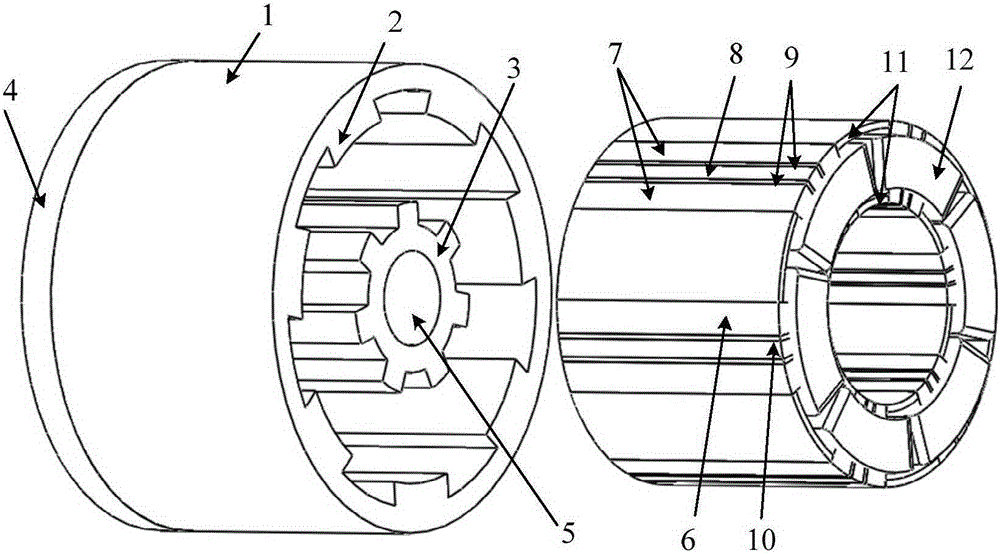
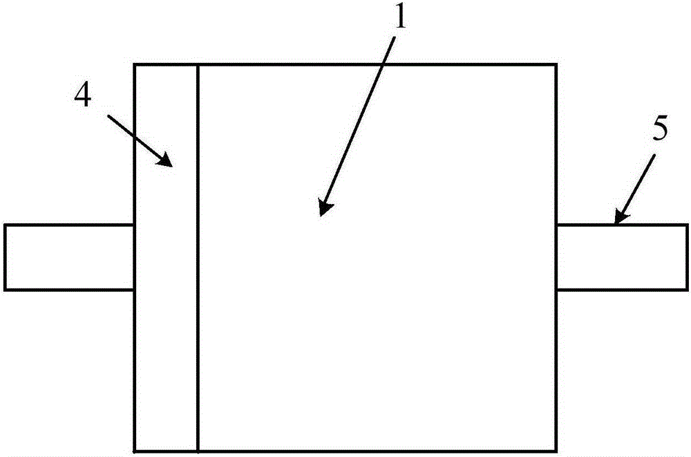
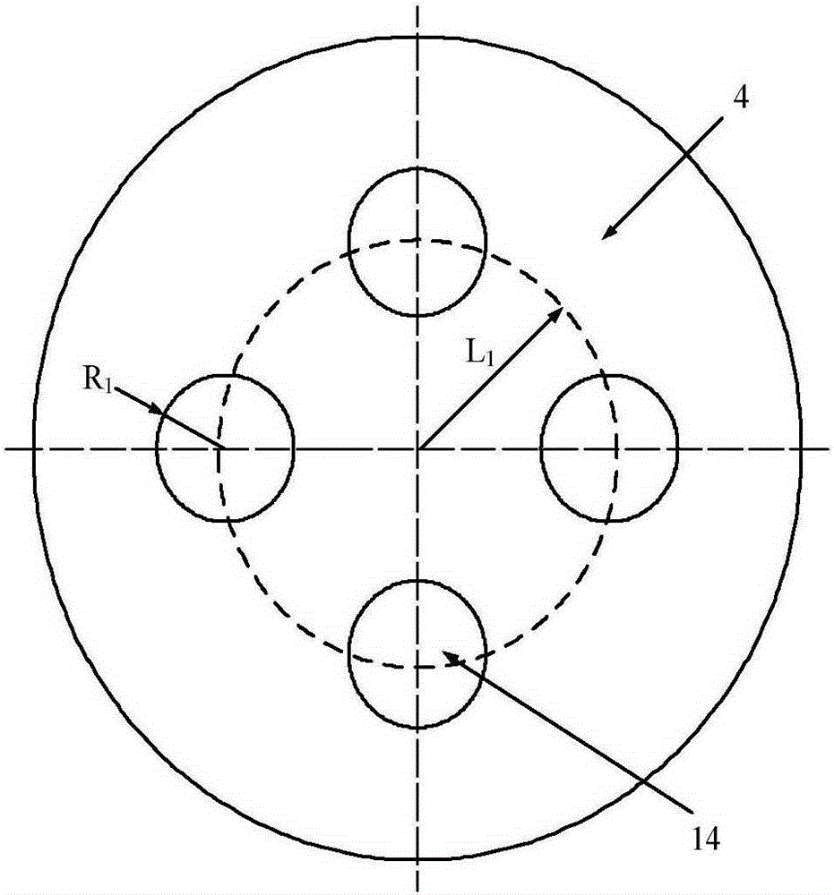
[0034] see figure 1 and figure 2 , the present invention is made up of double rotor 1, stator 6, armature winding 12 and nonmagnetic rotating shaft 5. Among them, the double rotor 1 is composed of an outer rotor core 2, an inner rotor core 3 and an annular disk 4. The inner rotor core 3 is coaxially spaced in the outer rotor core 2, and the outer rotor core 2 and the inner rotor core 3 is fixedly installed on the same end face of the axial direction with an annular disk 4, and the outer rotor core 2 and the inner rotor iron core 3 are fixedly connected together through the annular disk 4, and the connection method is riveting or welding, so that the double rotor 1 becomes A whole. The stator 6 is coaxially installed between the outer rotor iron core 2 and the inner rotor iron core 3, and the inner rotor iron core 3 is coaxially and fixedly sleeved outside the non-magnetic rotating shaft 5. The non-magnetic rotating shaft 5, the inner rotor iron core 3, the stator 6 and the...


PUM


Abstract

The present invention discloses a dual-rotor flux-switching motor for a vehicle. A stator is formed by three-phase armature winding, Ns stator core modules and Ns armature slots, Ns=3Nc, and Nc is the coil number of single-phase windings. The Ns stator core modules are uniformly distributed along a circumferential direction. An armature slot is arranged between each two stator core modules, and the three-phase armature winding is placed in the armature slots. A hybrid permanent magnet module is fixedly embedded at the middle of each of the stator core modules along a radial direction. Each of the hybrid permanent magnet modules is formed by a ferrite permanent magnet and two identical NdFeB permanent magnets, and the ferrite permanent magnet and the NdFeB permanent magnets at two sides are closely and seamlessly connected. A significant series magnetic circuit is formed in the magnet flux path of two adjacent permanent magnets. Compared with a traditional magnet flux switching permanent magnet motor in a parallel magnetic circuit, the stator tooth part easy saturation problem is significantly improved, and the utilization rate of the permanent magnet is effectively improved.

Description

technical field [0001] The invention belongs to the technical field of motor manufacturing, in particular to a double-rotor magnetic flux switching motor used for electric vehicles and the like. Background technique [0002] The flux switching motor adopts the stator permanent magnet structure. The armature winding and permanent magnet are located on the stator. There is neither armature winding nor permanent magnet on the rotor. The structure is simple, the operation is reliable, and the efficiency and power density are high. On the one hand, this type of flux switching motor following the principle of flux switching can greatly reduce or offset the high-order harmonic components in the permanent magnet flux linkage and induced electromotive force of a single winding coil due to the complementarity of the windings, making the motor in the use of Under the condition of centralized armature winding and rotor straight slot, high sinusoidal no-load permanent magnet flux linkage...

Claims


Application Information

Patent Timeline
IPC IPC(8): H02K16/02H02K1/17H02K1/02H02K1/24H02K1/32
CPCH02K1/02H02K1/17H02K1/24H02K1/32H02K16/02H02K2201/03
Inventor 朱孝勇张超全力杜怿
Owner JIANGSU UNIV
Why Eureka
Try Eureka