Steam condensation system for a granulation installation

A granulation equipment, steam condensation technology, used in lighting and heating equipment, cooling devices, processing discharged materials, etc., to reduce environmental impact, increase operational safety, and save capital and operating expenses

Inactive Publication Date: 2016-02-24
PAUL WURTH SA
View PDF10 Cites 0 Cited by
  • Summary
  • Abstract
  • Description
  • Claims
  • Application Information

AI Technical Summary

Problems solved by technology

However, such systems require additional investment

Method used


Image

  • Steam condensation system for a granulation installation
  • Steam condensation system for a granulation installation

Examples


Embodiment Construction

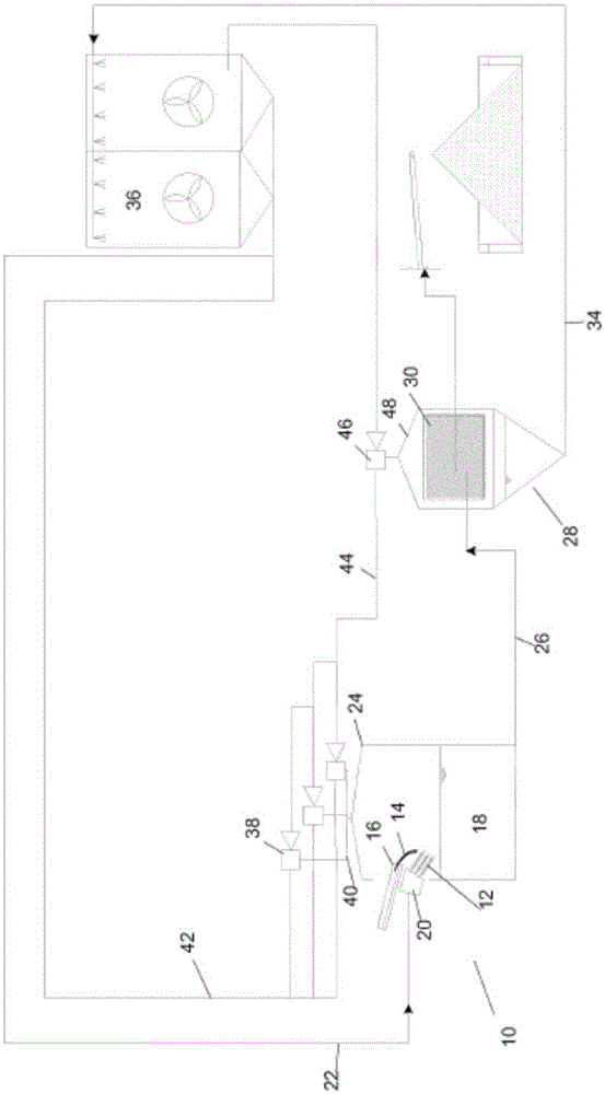
[0042] To illustrate an embodiment of the invention, figure 1 A schematic diagram of a granulation plant 10 designed for slag granulation in a blast furnace plant (which is not shown) is shown. In general, the apparatus 10 is thus used to granulate a stream of molten blast furnace slag by quenching it with one or more jets 12 of relatively cool granulation water. Such as figure 1 As shown, molten slag stream 14 , which inevitably flows out of the blast furnace together with pig iron, falls from hot melt launder end 16 into granulation tank 18 . During operation, a jet of granulated water 12 impinges on molten slag 14 falling from the end 16 of the hot runner, the jet of granulated water being pumped by one or more parallel high pressure pumps (not shown) via A water injection device 20 (also commonly referred to as a "spray box") is supplied by a supply pipe 22 . A suitable configuration of the water injection device 20 is eg described in patent application WO2004 / 048617. ...


PUM


Abstract

The present invention concerns a granulation installation (10) for granulating molten material produced in a metallurgical plant. The installation comprises a water injection device (20), for injecting granulation water into a flow of molten material (14) to granulate the molten material, a granulation tank (18) for collecting the granulation water and the granulated material. The installation further comprises a steam collecting hood that includes an evacuation device for evacuating steam from said hood, condensing said steam and evacuating said condensed steam to the atmosphere.

Description

technical field [0001] The present invention generally relates to a granulation plant for molten material, in particular for metallurgical smelts such as blast furnace slag. The present invention more particularly relates to an improved vapor condensing system for use in such equipment. Background technique [0002] An example of a modern granulation plant of this type, in particular for molten blast furnace slag, is shown in accompanying drawing 2, published in Iron & Steel Technology, Issue 4, 2005 titled " Slaggranulationsystem-Environmentalprocesscontrol( Slag Granulation System-Environmental Treatment Control)" article. As shown in Figure 2, this type of equipment usually includes: water injection device [2] (also known as water spray box), which is used to Granulation water is injected into the flow of molten material (eg slag) received via the end of the launder [1]. Granulation of the molten material is thereby achieved. The plant also has a granulation tank [3]...

Claims


Application Information

Patent Timeline
Patent Type & Authority Applications(China)
IPC IPC(8): C21B3/08F27D15/02
CPCC21B3/08C21B2400/062C21B2400/024C21B2400/08F27D15/0286Y02P10/25C21B7/10
Inventor 霍斯特·卡佩斯马克·史怀哲汤米·马修
Owner PAUL WURTH SA
Why Eureka
Try Eureka