Rolling bearing unit with combination seal ring

A combined sealing and rolling bearing technology, used in rolling contact bearings, bearing components, bearings in rotating motion, etc., can solve the problems of reduced interference, inability to shorten the overall length, and small thickness and size, and achieve the purpose of suppressing the increase of sliding torque, The effect of preventing the reduction of life and good sealing performance

Inactive Publication Date: 2016-02-24
NSK LTD
View PDF10 Cites 10 Cited by
  • Summary
  • Abstract
  • Description
  • Claims
  • Application Information

AI Technical Summary

Problems solved by technology

However, the technology disclosed in Patent Document 3 is aimed at the side lip that functions to prevent the intrusion of foreign matter into the internal space of the bearing, and it is not possible to apply the value of the appropriate interference amount for such a side lip as it is to a side lip whose overall length is shorter than that of the side lip, Auxiliary lip with small thickness (low rigidity)
In addition, when the value of the interference is set to be large, due to the sliding contact between the tip edge of the auxiliary seal lip and the axially outer surface of the rotation side annular portion constituting the slinger, Frictional resistance, there is a possibility of deformation such as a phase shift (delay) of the terminal part relative to the base end part in the circumferential direction
Furthermore, the full length in the axial direction of the free state of the auxiliary seal lip is L 2 In the case of such deformation, the axial full length of the auxiliary sealing lip from L 2 reduced to L 2 cosα (α: the deviation angle in the circumferential direction between the tip end and the base end), so the actual value of the interference will decrease, and only the sliding torque (sealing torque) will increase.

Method used


Image

  • Rolling bearing unit with combination seal ring
  • Rolling bearing unit with combination seal ring
  • Rolling bearing unit with combination seal ring

Examples


Embodiment

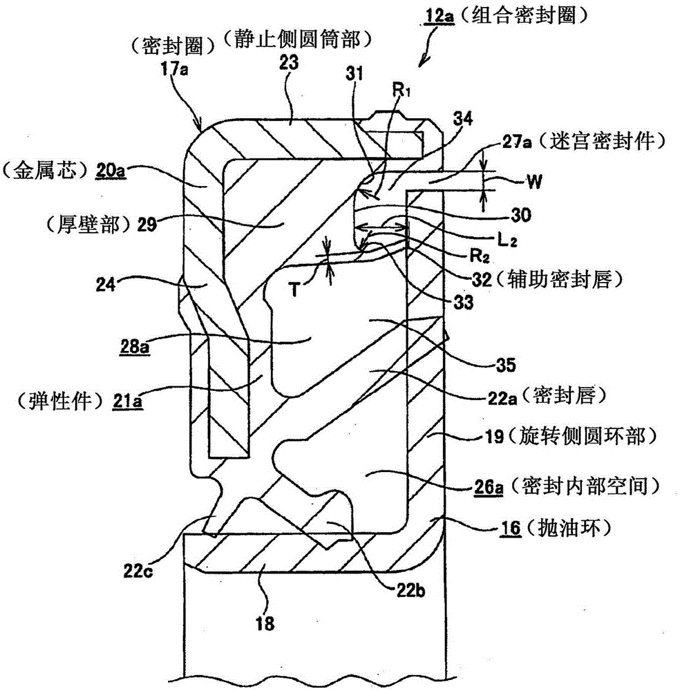
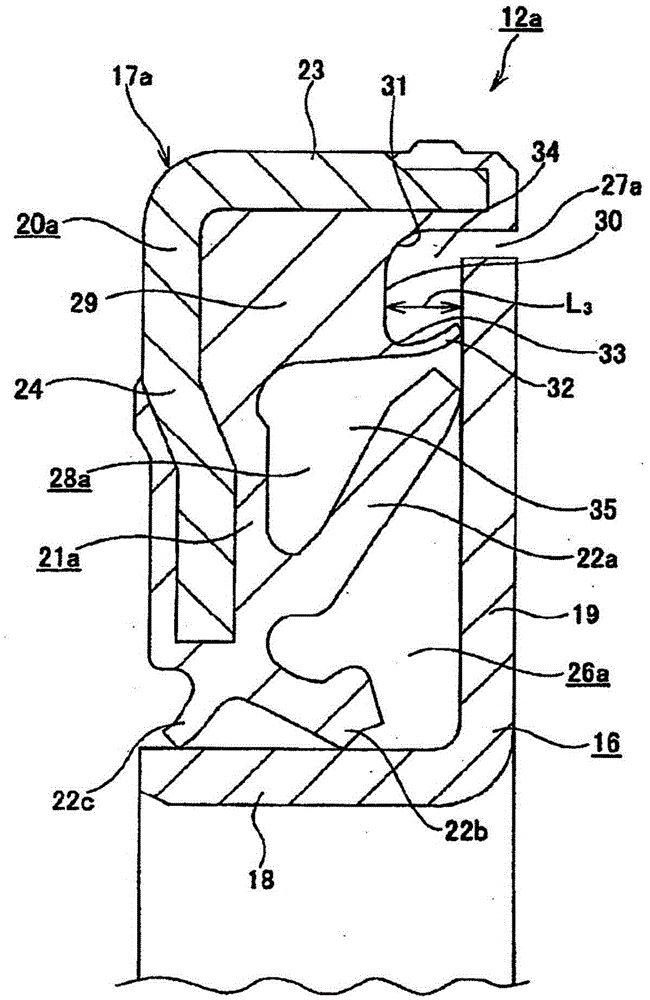
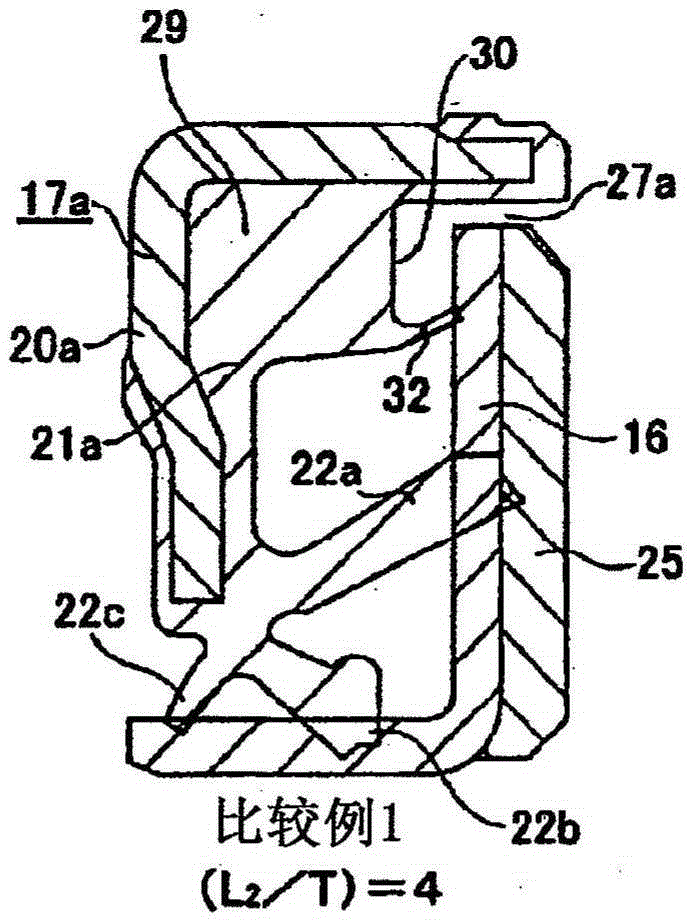
[0133] Next, experiments conducted to confirm the effects of the present invention will be described. In this experiment, the purpose of investigating the relationship between the axial full length and the thickness dimension of the auxiliary sealing lip 32 in a free state (L 2 / T), and the size of the interference of the auxiliary sealing lip 32 on the life of the combined sealing ring and the influence of the torque. When carrying out this experiment, the outer diameter is 75mm, the inner diameter is 61mm, the assembly width is 5mm, and the encoder 25 is attached and supported on the axial inner surface of the oil flinger 16. Figure 3A-3E Sample of 5 combined seals shown. Figure 3B , 3C Examples 1 and 2 show that the full axial length of the auxiliary seal lip 32 in a free state is within the range of 5.5 to 7.5 times the thickness dimension. Wherein embodiment 1 (L 2 / T) value is 5.5 times, embodiment 2 (L 2 / T) is 7.5 times. In contrast, Figure 3A , 3D Comparati...


PUM


Abstract

In order to implement a structure capable of ensuring the movement of a seal lip (22a) provided in a seal ring (17a) by preventing the entry of foreign matter into a seal interior space (26a) between a slinger (16) and the seal ring (17a) which constitute a combination seal ring (12a), a labyrinth seal (27a) is provided between the outer peripheral edge of a rotation-side circular ring section (19) constituting the slinger (16) and the inner peripheral surface of a stationary side cylindrical section (23) of a cored bar (20) constituting the seal ring (17a). Further, in a portion which is a part of an elastic material (21a) constituting the seal ring (17a) and is located between the labyrinth seal (27a) and the seal lip (22a) being a side lip, an auxiliary seal lip (32) having lower rigidity than the seal lip (22a) is provided. The total axial length of the auxiliary seal lip (32) in a free state is set to 5.5 to 7.5 times the thickness thereof, and the proportion of an interference is set to the range of 0-20% of the total axial length in a free state.

Description

technical field [0001] The present invention relates to an improvement of a rolling bearing unit with a composite seal ring, which is used, for example, in a rolling bearing unit for freely rotatably supporting a wheel of an automobile relative to a suspension device, by using an oil flinger and a seal. A rolling bearing unit formed by sealing the end opening of the internal space of the bearing with a combined sealing ring composed of a ring. A plurality of rolling bodies are provided. Background technique [0002] [Description of Prior Art] [0003] As a rolling bearing unit for freely rotatably supporting the wheels and the like of an automobile with respect to the suspension device, for example, Patent Document 1 discloses Figure 7 The structure of the rolling bearing unit for wheel support is shown. Should Figure 7 In the shown rolling bearing unit 1 , an outer ring 2 that is a stationary side raceway ring and a hub 3 that is a rotating side raceway ring are arrange...

Claims


Application Information

Patent Timeline
Patent Type & Authority Applications(China)
IPC IPC(8): F16C33/78F16C19/18F16J15/32F16J15/447F16J15/3232F16J15/3256
CPCF16J15/3264F16C33/7883F16C19/186F16C2326/02F16C33/805
Inventor 塩野泰宏若林达男
Owner NSK LTD
Why Eureka
Try Eureka