Eureka AIR delivers breakthrough ideas for toughest innovation challenges, trusted by R&D personnel around the world.

Automatic feeding, positioning and punching device

A technology of automatic feeding and positioning punching, applied in the direction of feeding device, positioning device, storage device, etc., can solve the problems of high labor intensity, low production efficiency, error accumulation, etc., achieve high degree of automation, high maintenance cost, positioning Small error effect

Active Publication Date: 2016-03-02
CHINA HANGFA GUIZHOU LIYANG AVIATION POWER CO LTD
View PDF7 Cites 3 Cited by
  • Summary
  • Abstract
  • Description
  • Claims
  • Application Information

AI Technical Summary

Problems solved by technology

[0006] There is a problem of error accumulation in the positioning of this progressive method. In general, the positioning part should be as close as possible to the size of the positioning feature. When working, the positioning part should be able to enter the positioning hole of the part smoothly. The size of the positioning part must be smaller than the size of the part feature. Therefore, there is always a gap between the positioning part and the positioning feature. As the stamping process progresses, the error gradually accumulates. The cumulative error of the product will cause the front and rear processing positions to exceed the size range required by the product, and in the case of mass production, manual positioning, The workload of the workers is heavy, the labor intensity is high, the production efficiency is low, and the safety is not good

Method used


Image

  • Automatic feeding, positioning and punching device
  • Automatic feeding, positioning and punching device
  • Automatic feeding, positioning and punching device

Examples


Embodiment Construction

[0021] The technical solution of the present invention is further described below, but the scope of protection is not limited to the description.

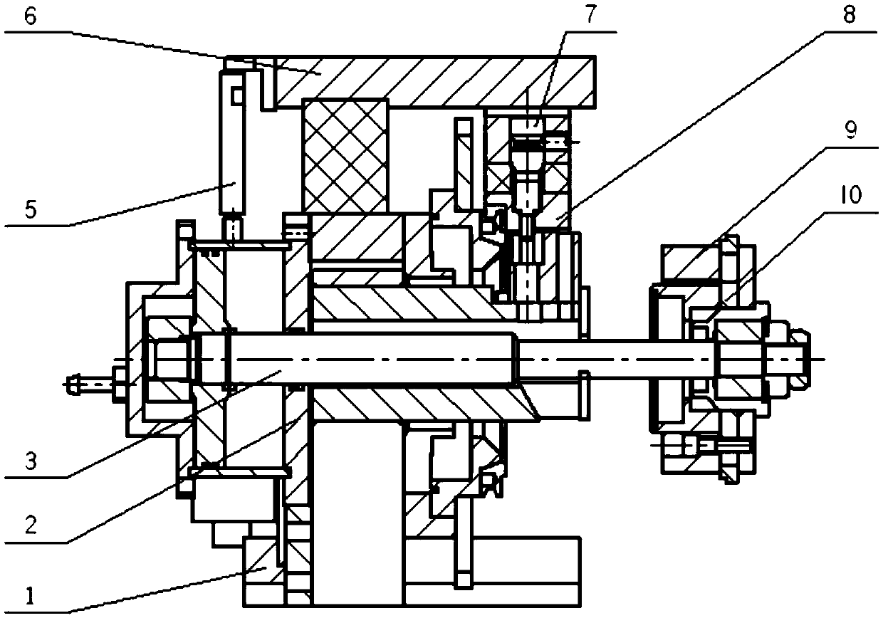
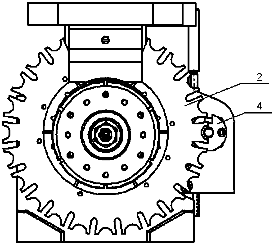
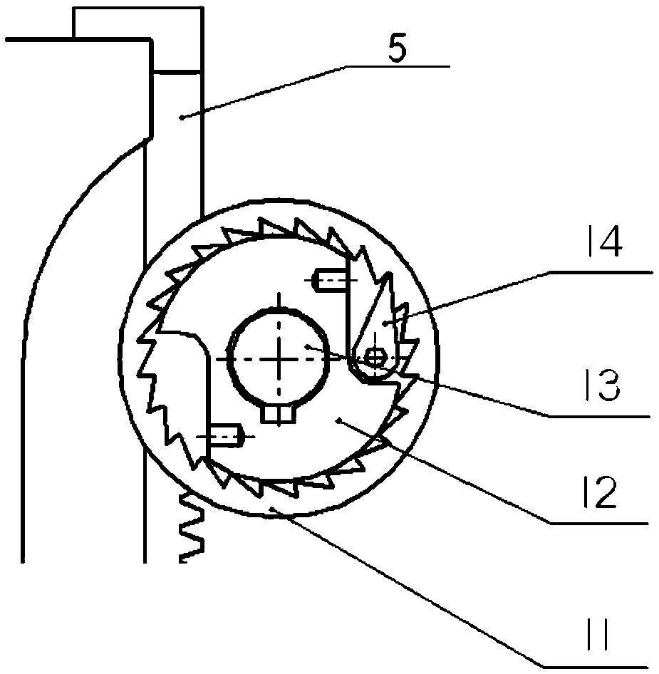
[0022] Such as Figure 1 to Figure 3 The shown automatic feed positioning punching device includes a body 1, a transmission shaft 3, a rack 5, an upper plate 6, a punch 7, a die 8, a positioning block 10, a ratchet gear 11, and a ratchet shaft 13; The body 1 is an L-shaped frame, the top of the body 1 is equipped with an upper template 6 that can move up and down, and the middle part of the body 1 is equipped with a rotatable transmission shaft 3 in the same direction as the upper template 6; the upper template 6 The bottom of the front end of the front end is fixed with a punch 7, and the rear end of the upper template 6 is fixed on the upper end of the vertically arranged rack 5, and the lower end of the rack 5 is engaged with the ratchet gear 11; the front end of the transmission shaft 3 exceeds the upper end of the upper templa...


PUM


Abstract

The invention provides an automatic feeding, positioning and punching device which comprises a body base, a transmission shaft, a rack, an upper die plate, a male die, a female die, a positioning block, a ratchet and a ratchet shaft, wherein the body base is an L-shaped rack; the upper die plate capable of moving up and down is mounted at the top of the body base; and the rotatable transmission shaft is mounted in the middle of the body base in the same direction as the upper die plate. Through the ratchet and an index plate structure, a part can move equidistantly in the circumferential direction by virtue of back and forth movement of a punch and mechanical transmission switching, machining the part at a required position is ensured, the part is rotated and positioned accurately, the positioning error is small, the degree of overall automation is high, the machining process doesn't need to be controlled manually, the part can be machined continuously until all holes are finished in sequence, and the problems of high worker learning cost and high maintenance cost caused by the reason that rotation is controlled by a numerical control system are solved.

Description

technical field [0001] The invention relates to an automatic feeding positioning punching device, which belongs to the field of small-sized sheet metal processing. Background technique [0002] Such as Figure 5 The annular flame tube shown is the main part of the current aero-engine structure. Since the engine has high-temperature gas in the core part, the flame tube works in the high-temperature and high-pressure airflow. It is a ring-shaped sheet metal structure, and at the same time, certain small holes are evenly distributed on the surface of the part, and the groove-shaped features are used to introduce external air, cool the wall of the flame tube, improve the working life and high-temperature strength of the flame tube, and introduce airflow to participate in combustion at the same time. Improve fuel combustion efficiency. [0003] Specifically, the flame tube is a small-diameter thin-walled high-temperature alloy annular part, with 24 small holes with a diameter of...

Claims


Application Information

Patent Timeline
IPC IPC(8): B21D28/24B21D43/00B21D43/14
CPCB21D28/243B21D43/003B21D43/14
Inventor 田孟良窦一涛
Owner CHINA HANGFA GUIZHOU LIYANG AVIATION POWER CO LTD
Why Eureka
Eureka Blog
Learn More