Longitudinal driving device for numerical control lathe

A driving device, CNC lathe technology, applied in feeding devices, metal processing mechanical parts, metal processing equipment and other directions, can solve the problems of affecting processing accuracy, wire nut damage, falling deformation, etc., to improve processing accuracy, easy to replace parts, Resolving the effect of resonance

Inactive Publication Date: 2016-03-02
SHIYAN OUKAI IND & TRADE
View PDF1 Cites 0 Cited by
  • Summary
  • Abstract
  • Description
  • Claims
  • Application Information

AI Technical Summary

Problems solved by technology

However, for lathes with a bed of more than 2 meters, this drive device will have some disadvantages: First, because the screw rod is too long, its own weight will be inverted and deformed in the middle, causing vibration during operation, and in a certain speed range will resonate
This resonance will lead to a decrease in the surface finish of the product processing, an increase in the size deviation, and even vibration marks on the product processing surface, which seriously affects the processing accuracy; secondly, due to the resonance, the fixing seats at both ends of the bed will be damaged to varying degrees and affect their life. ; The third is that when the large pallet moves on the screw, since the power of the long screw is from the servo motor or stepping motor at the end of the bed, the relative tension will be generated on the long screw, which will affect its processing accuracy
[0003] The patent No.: 200820230136.1 is the transmission device of CNC gantry milling machine. In this patent document, the screw is fixed, and the motor drives the nut along the screw to move, but it uses the stretching flange to pre-tighten the screw to tension. Although the tension flange pre-tightens the screw rod during use, the unreasonable structure will also cause damage to the screw nut, thus affecting the use effect

Method used


Image

  • Longitudinal driving device for numerical control lathe
  • Longitudinal driving device for numerical control lathe

Examples


Embodiment Construction

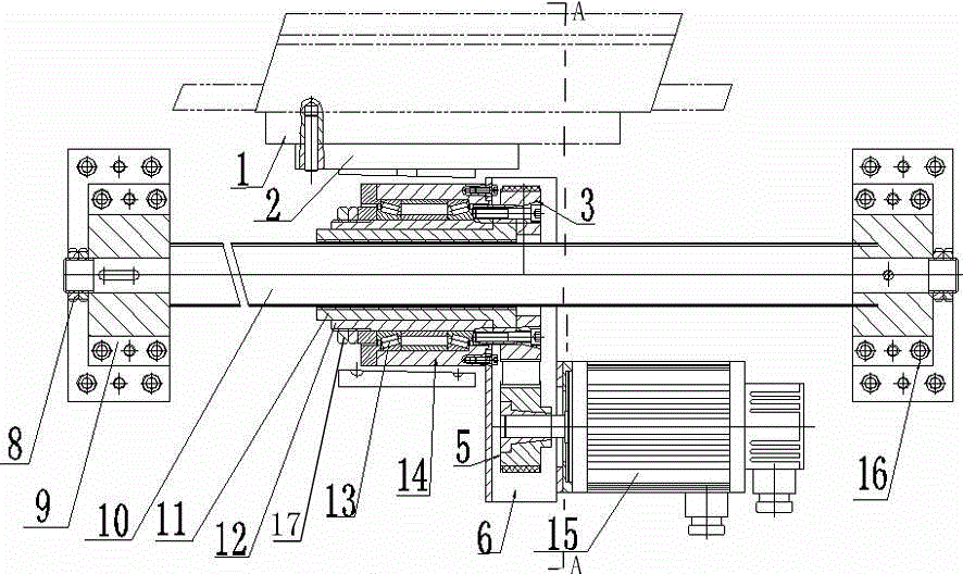
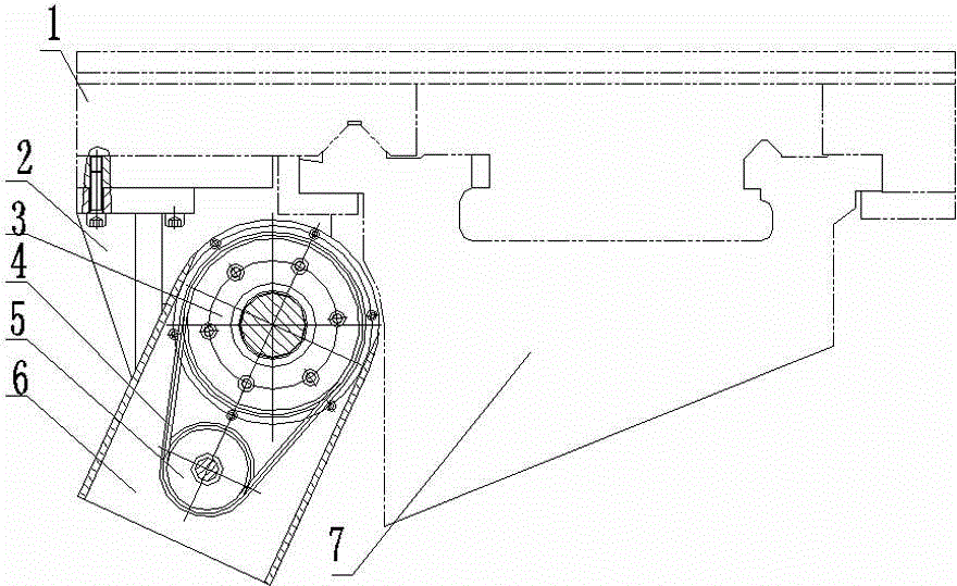
[0015] The present invention as figure 1 , 2 shown

[0016] Including the lathe bed 7, the lathe bed 7 is provided with a large supporting plate 1, and a ball screw 10 is arranged under the lathe bed 7, and one end of the ball screw 10 is fixed on its tail end 16, and the other end passes through the fixed support. Seat 9 is fastened with nut-8; ball screw 10 is screwed with nut 11, and transition sleeve 12 is arranged outside nut 11, and double thrust bearing 13 is arranged outside transition sleeve 12, and double thrust bearing 13 is provided with bearing Seat 14; one end of transition sleeve 12 and screw nut 11 is fixed with pulley 1 3 by bolts, and the other end of transition sleeve 12 is provided with nut 2 17 to fix double thrust bearing 13 in bearing housing 14; Connecting bracket 2 is arranged, and bearing block 14 is fixed in connecting bracket 2; Connecting bracket 2 is also provided with motor bracket 6, is horizontally provided with servo motor 15 on motor bracke...


PUM


Abstract

The invention provides a longitudinal driving device for a numerical control lathe. One end of a ball screw is fixed to the tail end of a lathe body, and the other end of the ball screw penetrates a fixing support and is firmly fixed through a nut. A screw nut is screwed on the ball screw and is externally provided with a transition sleeve. The transition sleeve is externally provided with a dual thrust bearing which is externally provided with a bearing block. A first belt wheel is fixed to one end of the transition sleeve and one end of the screw nut through a bolt, and the other end of the transition sleeve is provided with a second nut to fix the dual thrust bearing in the bearing block. A connecting support is arranged below a large supporting plate, and the bearing block is fixed in the connecting support. A motor support is arranged below the connecting support, and a servo motor is transversely arranged on the motor support. The motor is provided with a second belt wheel. The first belt wheel and the second belt wheel are connected through a synchronous belt. According to the longitudinal driving device for the numerical control lathe, the screw nut drives the large supporting plate to move through the thrust bearing, the longitudinal driving device is suitable for lathes with the length larger than 2 m, the problem of resonance is solved, machining precision is improved, and the service life of the ball screw and the screw nut is prolonged.

Description

technical field [0001] The invention relates to the driving field of a numerical control lathe, in particular to a longitudinal driving device of a numerical control lathe. Background technique [0002] The longitudinal drive of the CNC lathe is generally to install a servo motor or a stepping motor at the original position of the tool box of the lathe or at the end of the bed, and use the servo motor or stepping motor to drive the screw to rotate. The screw nut is connected with the nut seat and the T-shaped bracket and fixed on the large pallet of the lathe. The servo motor or stepping motor drives the screw to rotate to realize the movement of the large pallet of the lathe. However, for lathes with a bed of more than 2 meters, this drive device will have some disadvantages: First, because the screw rod is too long, its own weight will be inverted and deformed in the middle, causing vibration during operation, and in a certain speed range will resonate. The resonance wi...

Claims


Application Information

Patent Timeline
Patent Type & Authority Applications(China)
IPC IPC(8): B23Q5/28
Inventor 刘宏伟
Owner SHIYAN OUKAI IND & TRADE
Why Eureka
Try Eureka