Double-oar damping rotor unmanned aerial vehicle
A technology of unmanned rotor and unmanned aerial vehicle, which is applied in the field of unmanned aerial vehicles, can solve the problems of inaccurate detection and unstable flight of unmanned aerial vehicles, achieve large load capacity, improve stability and obstacle avoidance ability, and easy to control the direction Effect
- Summary
- Abstract
- Description
- Claims
- Application Information
AI Technical Summary
Problems solved by technology
Method used
Image
Examples
Embodiment 1
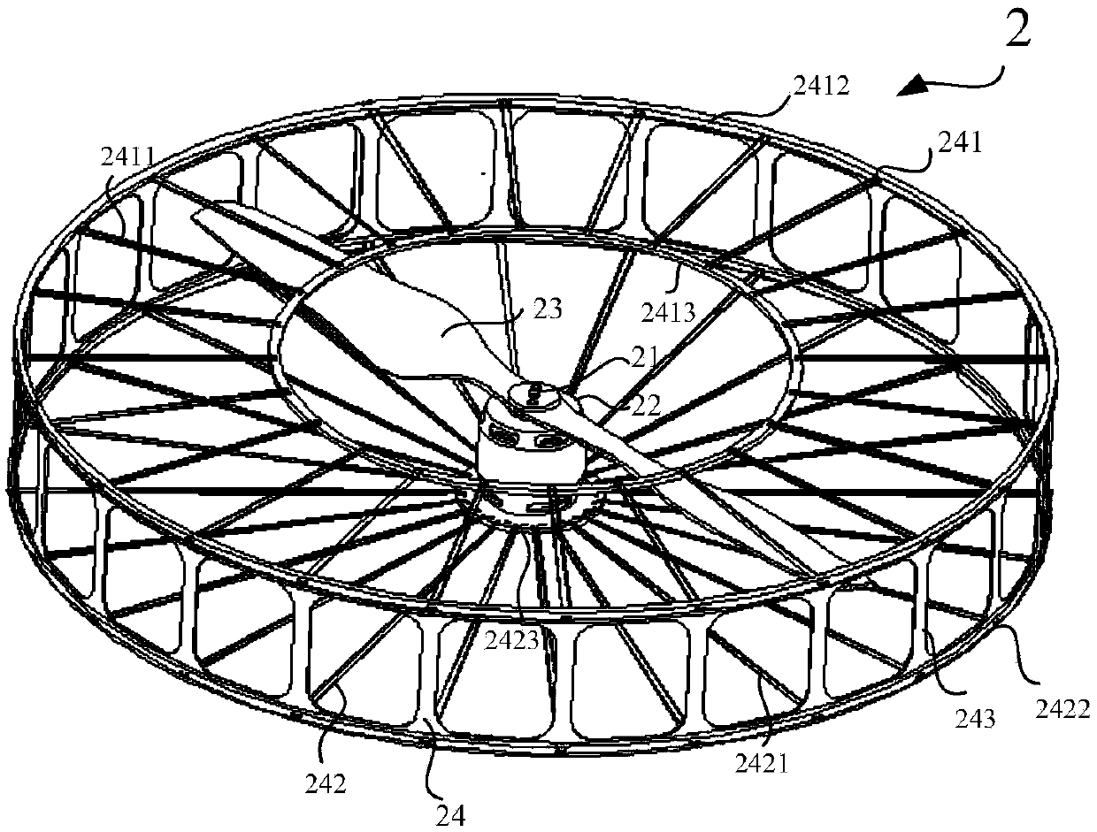
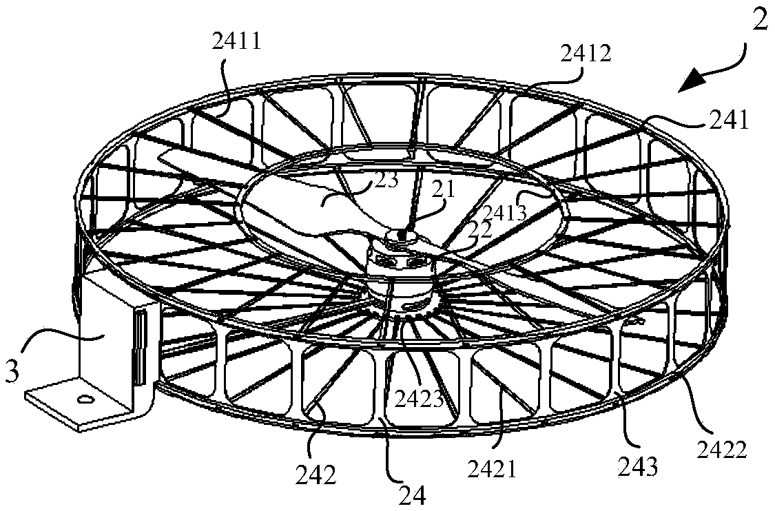
[0036] see figure 2 , the UAV rotor 2 includes a driving member 25 , a rotating shaft 21 , at least two paddles 23 and a mesh cover 24 . The driving member 25 is used to drive the rotating shaft 21 to rotate, the driving member 25 is specifically a motor, the rotating shaft 21 is connected with the driving member 25, and the rotating shaft 21 can rotate relative to its axis; The propeller hub 22 is connected to the rotating shaft 21 in a rotational manner, and the propeller hub 22 is used for fixedly connecting the at least two propeller blades 23 ; The axis is rotatably connected to the hub 22 .
[0037]The net cover part 24 is detachably fixedly connected with the fuselage 1 , and the net cover part 24 includes a front net cover 241 , a rear net cover 242 and a plurality of connecting beams 243 . The front mesh cover 241 includes a plurality of first mesh frames 2411, a first outer ring 2412 and a first inner ring 2413, and the two ends of each of the first mesh frames 24...
Embodiment 2
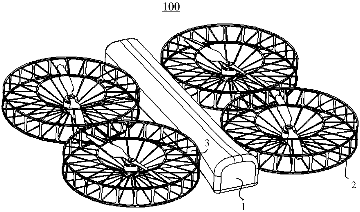
[0045] For the UAV rotor 2, the application also provides a dual-blade rotor 2, please refer to Figure 12 , the UAV 100 includes a fuselage 1 and at least four rotors 2 fixedly connected to the fuselage 1, and the at least four rotors 2 include a drive member 25, a rotating shaft 21, a hub 22, blades 23 and support frame 26.
[0046] The driving member includes a first motor 25a and a second motor relatively fixedly connected to the first motor 25a; the rotating shaft 21 includes a first rotating shaft 21a and a second rotating shaft 21b, and the first rotating shaft 21a The second rotating shaft 21b is connected to the first motor 25a and the second motor 25b respectively, and the first rotating shaft 21a and the second rotating shaft 21b can rotate relative to their axes respectively. The propeller hub 22 includes a first propeller hub 22a and a second propeller hub 22b, the first propeller hub 22a and the second propeller hub 22b are rotatably connected to the first rotat...
Embodiment 3
[0069] The method for measuring the distance and avoiding obstacles of the UAV is illustrated below. The method of measuring the distance and avoiding obstacles of the UAV is specifically described by presetting the grid number of the grating emitted by the grating transmitter. Figure 9 , the grating emitted by the grating emitter is a 3×3 grating. Figure 9 It can be seen from the above that the farther the obstacle is from the UAV, the larger the size of each raster that is launched onto the obstacle, and the same is mapped to the size of each raster on the photo taken by the shooting camera. bigger. Figure 9 middle a 1 , a 2 , a 3 and a 4 The distance from the drone is equal, and is mapped to each raster grid a on the photo taken by the shooting camera 1 and a 2 , a 2 and a 3 , a 3 and a 4 distances are equal, and d 1 and d 1 The spacing between a1 and a is greater than 2 spacing between. Calculate the distance between each part of the obstacle and the UAV a...
PUM
 Abstract
Description
Claims
Application Information
 - R&D
- Intellectual Property
- Life Sciences
- Materials
- Tech Scout
- Unparalleled Data Quality
- Higher Quality Content
- 60% Fewer Hallucinations
Browse by: Latest US Patents, China's latest patents, Technical Efficacy Thesaurus, Application Domain, Technology Topic, Popular Technical Reports.
© 2025 PatSnap. All rights reserved.Legal|Privacy policy|Modern Slavery Act Transparency Statement|Sitemap|About US| Contact US: help@patsnap.com


