Method and device for winding a crosswound bobbin

A winding device and bobbin technology, applied in the direction of transportation and packaging, thin material handling, and delivery of filamentous materials, etc., can solve the problems of damage to yarn quality, yarn quality reduction, yarn breakage, etc., and increase energy consumption Effect

Active Publication Date: 2016-03-02
SAURER SPINNING SOLUTIONS GMBH & CO KG
View PDF9 Cites 4 Cited by
  • Summary
  • Abstract
  • Description
  • Claims
  • Application Information

AI Technical Summary

Problems solved by technology

[0005] Therefore, the winding speed is chosen to be as high as possible in view of maximizing the productivity, but wherein at extremely high speeds the yarn quality (with especially increased pile) decreases and yarn breakage occurs to a large extent, which On the one hand, the yarn quality can also be compromised by the thread connection thus required, and on the other hand, the maximum achievable productivity is limited by the resulting production interruption for rewiring and by restarting the winding process.
In this regard, the state-of-the-art winding speed is selected to be as high as possible, as long as this is compatible with the required yarn quality and does not lead to too many yarn breaks which again lead to a reduction in productivity

Method used


Image

  • Method and device for winding a crosswound bobbin
  • Method and device for winding a crosswound bobbin
  • Method and device for winding a crosswound bobbin

Examples


Embodiment Construction

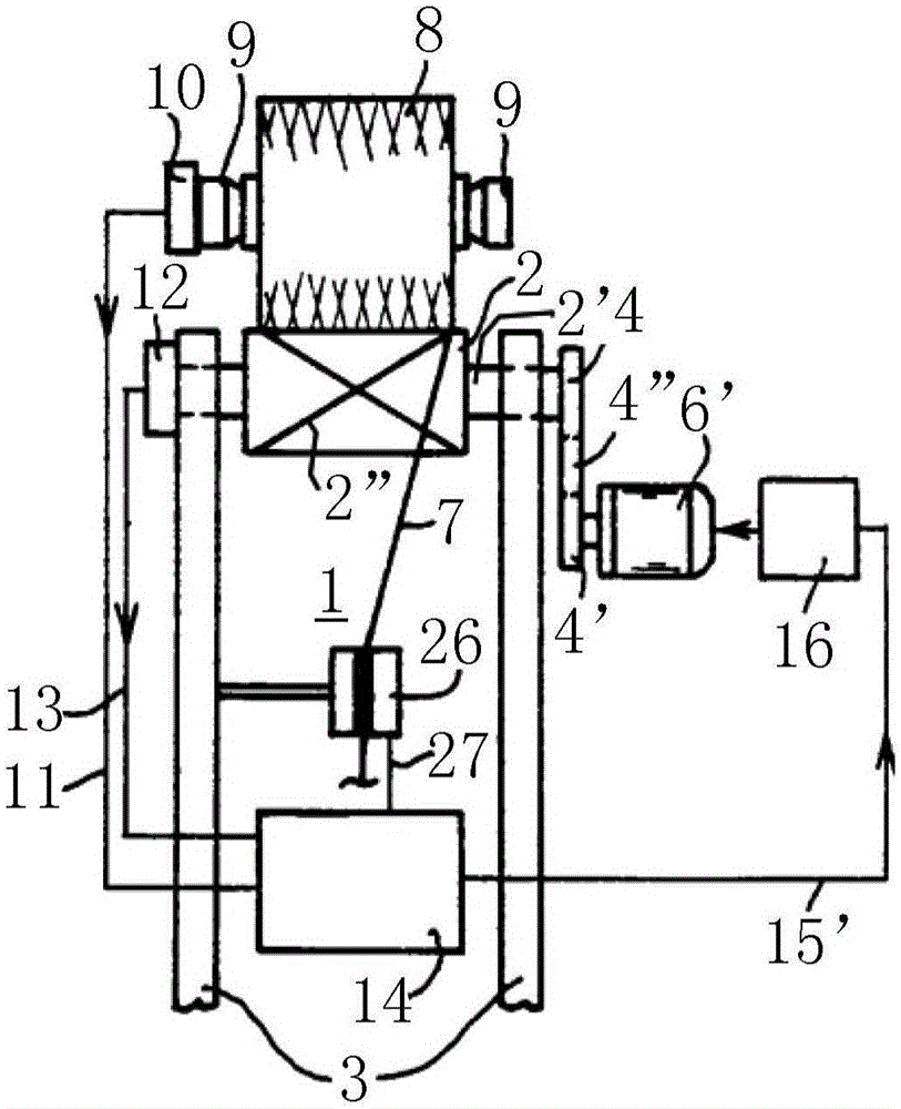
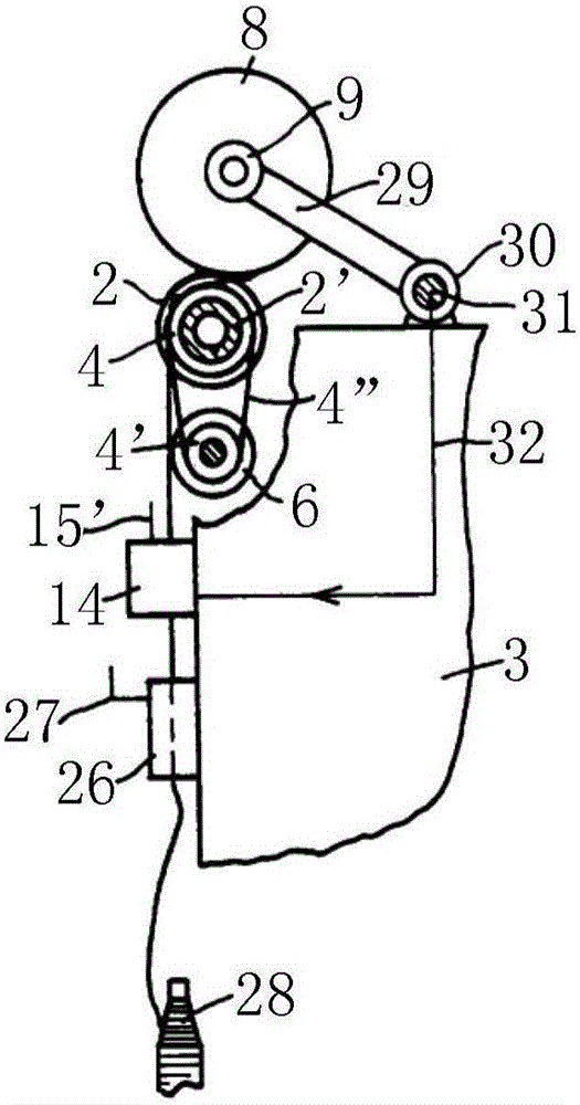
[0038] Basically quoted from EP0399243B1 (wherein figure 2 and Figure 5 shown) figure 1 and figure 2 The winding station 1 of the winding machine provided according to the invention is schematically shown in simplified front and side views.

[0039] At the winding station 1 , the winding bobbin 8 mounted in the bobbin holder 9 is frictionally driven by the drive drum 2 , which is wound by the winding station 1 in the form of a cross-winding bobbin 8 . The thread 7 drawn therein from the bobbin 28 is wound onto a cross-winding bobbin 8 . The wire 7 is arranged parallel to the axis of the cross-wound bobbin 8 by means of the helical groove 2" of the drive drum 2. The desired cross-wind is thereby produced.

[0040] The drive drum 2 is mounted on the frame 3 of the winder via a drum shaft 2'. The drive of the drum shaft 2' is achieved via belt pulleys 4 and 4' connected by a V-belt 4", wherein the belt pulley 4' is driven by an electric motor 6'. Instead of belt driv...


PUM


Abstract

The invention relates to a method and a device for winding a crosswound bobbin. The method is characterized in that winding operation is performed at the starting phase of a bobbin stroke at target value of winding speed; and the target value decreases relative to that of winding speed after the starting phase. The invention further relates to the device used for applying the method.

Description

technical field [0001] The invention relates to a winding method for winding bobbins and a device for carrying out the method. Background technique [0002] The winding bobbin is produced by the corresponding textile machine, which generally consists of a number of stations of the same type, each of which produces a winding bobbin, and these stations are centered with respect to the textile machine , for example powered by a power supply. In such a textile machine, which can in particular be an automatic winding machine, a plurality of relatively small winding bobbins, in particular bobbins, are wound into winding bobbins with significantly more yarn material, or It can also be a spinning machine. [0003] The winding process of the winding bobbin from the empty tube to the finished winding bobbin is called the bobbin stroke. In order to start the bobbin stroke, the finished winding bobbin is first removed from the station, e.g. by a service unit (responsible for several ...

Claims


Application Information

Patent Timeline
Patent Type & Authority Applications(China)
IPC IPC(8): B65H54/40
CPCB65H54/42B65H2701/31
Inventor T·福歇
Owner SAURER SPINNING SOLUTIONS GMBH & CO KG
Why Eureka
Try Eureka