
Steel ingot foot and manufacturing method thereof

A steel ingot and ingot foot technology, which is applied in the field of textile devices, can solve the problems of assembly error of steel ingot foot components, high consumption of steel material, and low product precision, and achieve the advantages of not easy to deflection, less steel material consumption, and simple molding process Effect

Active Publication Date: 2018-08-17
信阳市津乾机械设备制造有限公司
View PDF7 Cites 0 Cited by
  • Summary
  • Abstract
  • Description
  • Claims
  • Application Information

AI Technical Summary

Problems solved by technology

[0002] At the beginning of the development of the ingot feet, most of the ingot feet were cast iron feet. However, the cast iron ingot feet had the defect of microporous oil seepage and polluted cotton yarn, and were gradually replaced by steel ingot feet. However, the steel ingot feet on the market are usually manufactured in the form of assemblies. Although the manufacturing process is simple, a lot of steel material is lost in the process, and the final assembly of the manufactured steel ingot foot assembly will cause certain errors, resulting in low precision and high cost of the final product

Method used


Image

  • Steel ingot foot and manufacturing method thereof
  • Steel ingot foot and manufacturing method thereof
  • Steel ingot foot and manufacturing method thereof

Examples


Embodiment Construction

[0040] The technical solutions of the present invention will be described in further detail below through specific implementation methods.

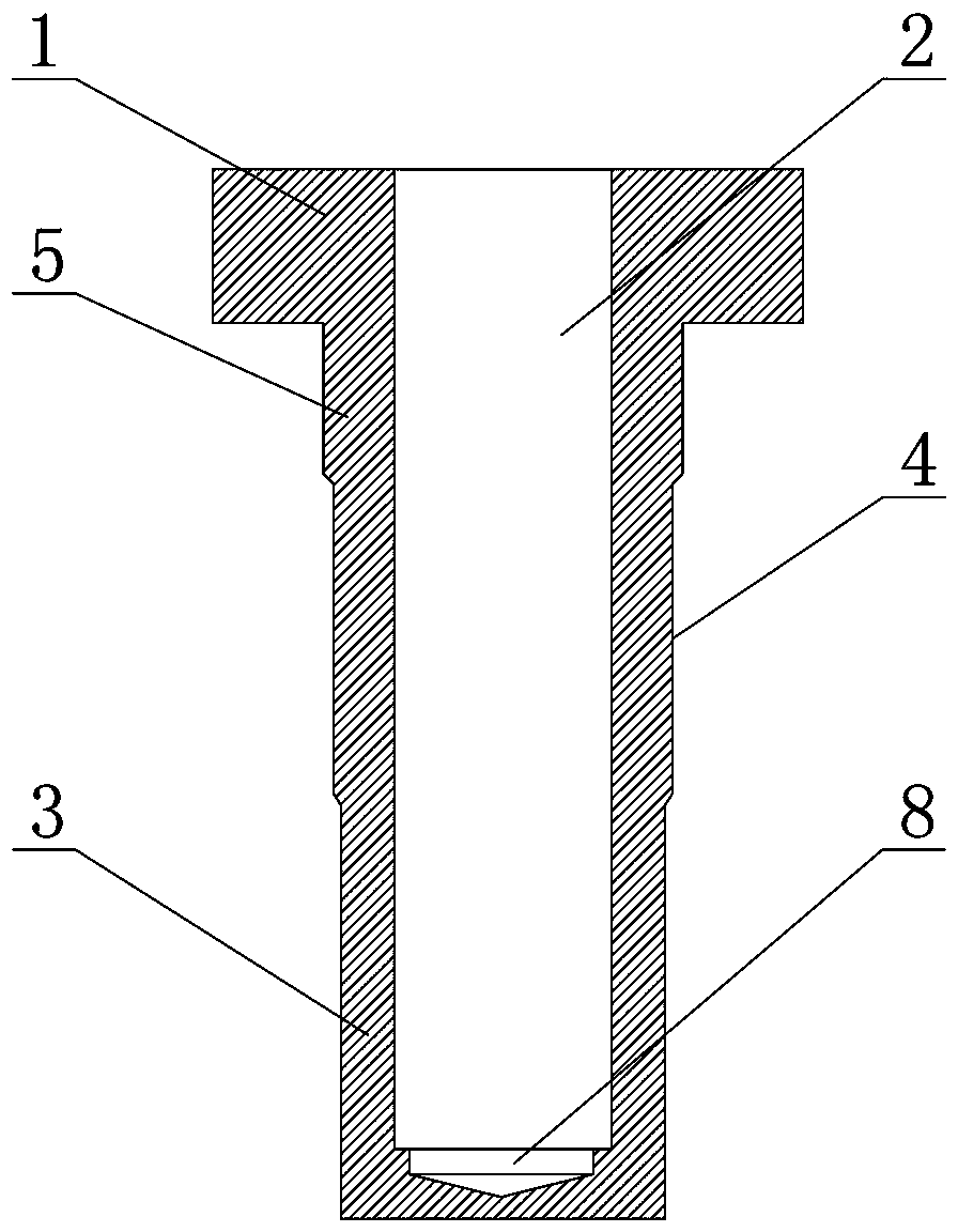
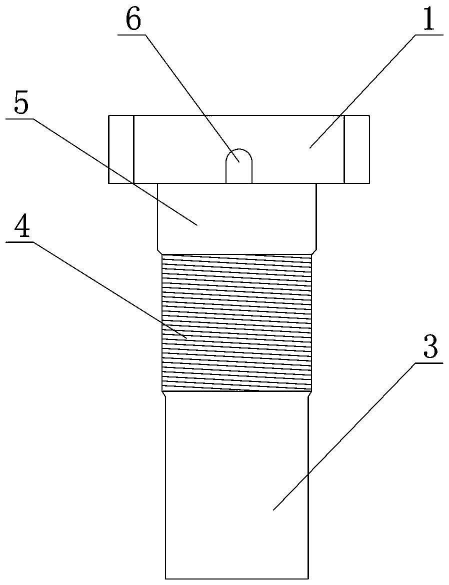
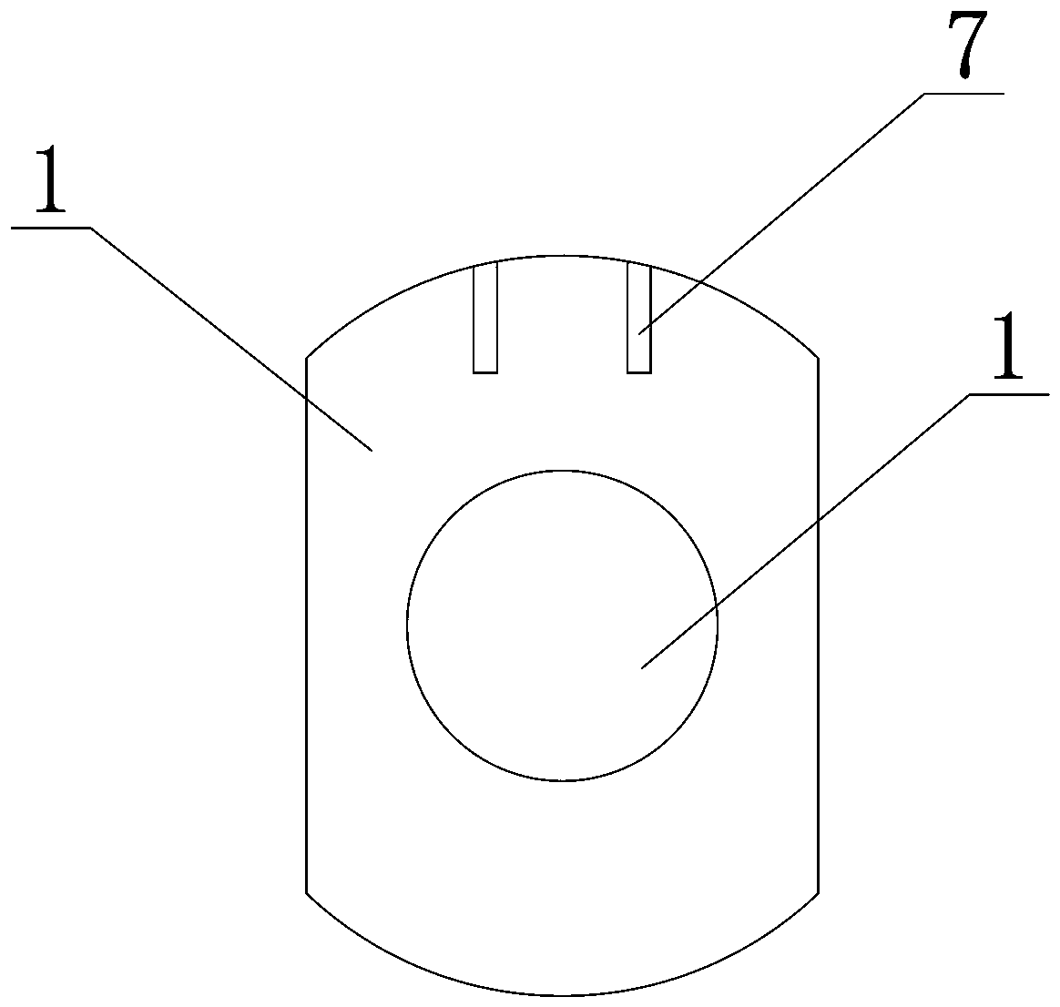
[0041] Such as Figure 1-3 As shown, a steel ingot foot includes a main body formed by integral cold heading and stamping. The blind hole 2 in the spindle foot 3 , wherein the opening of the blind hole 2 is set at the top of the flange 1 , and the bottom end of the blind hole 2 is stamped to form a boss 8 . The outer diameter of the spindle foot 3 decreases stepwise from the top to the bottom, at least one section of the outer wall of the stepped section is provided with threads 4 , and the uppermost section is a vertical positioning section 5 . The opposite two outer ends on the flange 1 are cut into a plane, and a spindle stopper groove 6 is provided on the plane, and the open end of the spindle stopper groove 6 is located at the lower end of the flange 1 . One of the arc ends of the flange 1 is provided with a double-slit ingot hook ...


PUM

PropertyMeasurementUnit
depthaaaaaaaaaa

Abstract

The invention provides an ingot foot. The ingot foot comprises a body formed through integrally cold upsetting and punching. The body comprises a flange formed through cold upsetting, an ingot foot formed by extending from the bottom end of the flange and a blind hole formed in the ingot foot through repeated punching, wherein an opening of the blind hole is formed in the top end of the flange, and a boss is formed at the bottom end of the blind hole through punching. As cold upsetting integral forming is adopted, the strength and the consistency of the ingot foot are guaranteed, material wastage is reduced due to the cold upsetting process, the structural strength and the performance of the ingot foot are better than the structural strength and the performance of an assembly ingot foot, and the production cost is low. The invention further provides a method for manufacturing the ingot foot. The method comprises the steps of cold upsetting forming of billet and finish machining and forming of a final product. Basic sizes of the blind hole, the flange and the ingot foot are formed through billet forming, and the requirement for accuracy of all parts is met through finish machining. The ingot foot has the advantages of being clear in labor division, simple in forming step, good in product strength and consistency and capable of greatly reducing the manufacturing cost.

Description

technical field [0001] The invention relates to a textile device, in particular to a steel ingot foot. It also relates to a method for manufacturing the ingot foot. Background technique [0002] At the beginning of the development of the ingot feet, most of the ingot feet were cast iron feet. However, the cast iron ingot feet had the defect of microporous oil seepage and polluted cotton yarn, and were gradually replaced by steel ingot feet. However, the steel ingot feet on the market are usually manufactured in the form of assemblies. Although the manufacturing process is simple, a lot of steel material is lost in the process, and the final assembly of the manufactured steel ingot foot assembly will cause certain errors, resulting in low precision and high cost of the final product. [0003] In order to solve the above existing problems, people have been seeking an ideal technical solution. Contents of the invention [0004] The purpose of the present invention is to add...

Claims


Application Information

Patent Timeline
Patent Type & Authority Patents(China)
IPC IPC(8): B23P15/00D01H7/12
CPCB23P15/00D01H7/12
Inventor 尤毅张志宇刘培银邬荣强
Owner 信阳市津乾机械设备制造有限公司
Learn More