Reinforced polyethylene complex pipeline
A technology of composite pipes and polyethylene, applied in the direction of pipes, rigid pipes, pipes/pipe joints/fittings, etc., can solve the problems of consuming manpower and material resources, reducing production efficiency, etc., to improve production efficiency, prolong service life, and use at low cost Effect
Inactive Publication Date: 2016-03-02
HAIXI HUAHUI CHEM MASCH CO LTD
View PDF3 Cites 5 Cited by
- Summary
- Abstract
- Description
- Claims
- Application Information
AI Technical Summary
Problems solved by technology
It is necessary to re-purchase pipes and re-lay pipes, again consuming manpower and material resources, and reducing production efficiency
Method used
View moreImage
Smart ImageViewing Examples

Examples
Embodiment Construction
Login to View More PUM
 Abstract
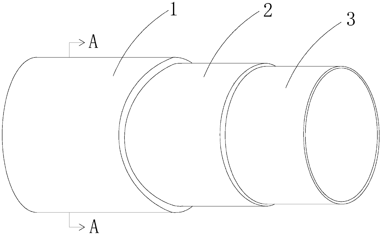
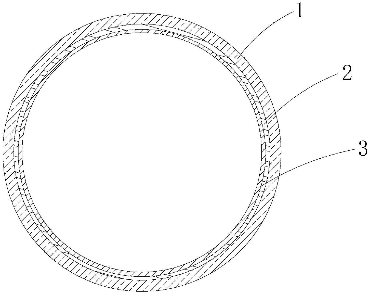
The invention relates to the technical field of oil, gas and chemical. A reinforced polyethylene complex pipeline comprises a carbon steel pipe layer, a high-density polyethylene layer and an ultra-high molecular weight polyethylene layer which are sequentially arranged from outside to inside, wherein the ultra-high molecular weight polyethylene layer and the high-density polyethylene layer are formed by melting ultra-high molecular weight polyethylene and high-density polyethylene at high temperature and high pressure and then co-extruding and forming through two die heads; a base pipe of the high-density polyethylene layer extends to the outer edge of a flange plate end surface of the carbon steel pipe layer along a pipe port in an outer layer; the carbon steel pipe layer, the high-density polyethylene layer and the ultra-high molecular weight polyethylene layer are integrally formed. The reinforced polyethylene complex pipeline is simple in structure, convenient to mount and connect, and low in use cost; the steel pipe layer and the high-density polyethylene layer at the outer layer can bear big pressure; the ultra-high molecular weight polyethylene layer at an inner layer has the effects of resisting abrasion, resisting impacting, resisting corrosion and self-lubricating. The abrasion resistance of the reinforced polyethylene complex pipeline is improved 7 to 10 times by being compared with that of a common metal conveying pipeline, thus the service life can be greatly prolonged, and the production efficiency is improved.
Description
technical field The invention relates to the technical field of oil and gas chemical industry, in particular to a reinforced polyethylene composite pipe used in the oil and gas chemical industry for the transportation of oil, gas and related materials. Background technique In recent years, plastic pipes have developed rapidly, and many new types of plastic pipes are being popularized and applied. It is a major trend to replace steel with plastic. As a new material with particularly excellent properties, ultra-high molecular weight polyethylene pipes are gradually recognized by the market. But at present, domestically produced polyethylene plastic pipes are mostly used in gas and water projects in the fields of gas, chemical industry, tap water, power plants, aluminum plants and the like. However, in the fields of gold mine, copper mine, coal mine, salt lake chemical industry, oil and gas chemical industry, etc., the friction of the powder material on the pipe is relatively...
Claims
Login to View More Application Information
Patent Timeline
 IPC IPC(8): F16L9/147
CPCF16L9/147
Inventor 金红祥
Owner HAIXI HUAHUI CHEM MASCH CO LTD