A rolled membrane element and its rolling method
A roll-type membrane and membrane element technology, applied in chemical instruments and methods, membrane technology, semi-permeable membrane separation, etc., can solve the problems of reduced product water desalination rate, reduced water production of components, high osmotic pressure of concentrated water, etc. Filtration performance, high water yield, water quality improvement effect
- Summary
- Abstract
- Description
- Claims
- Application Information
AI Technical Summary
Problems solved by technology
Method used
Image

Examples
Embodiment 1
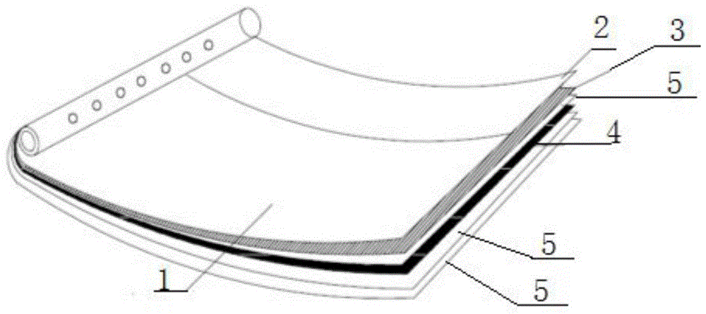
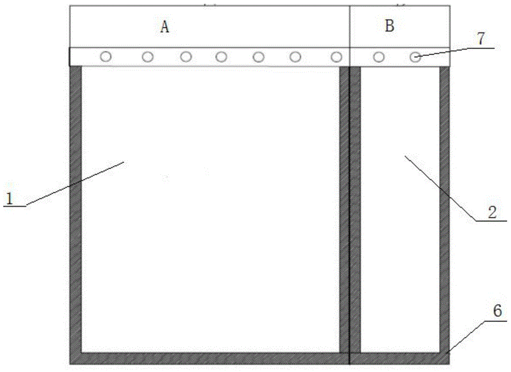
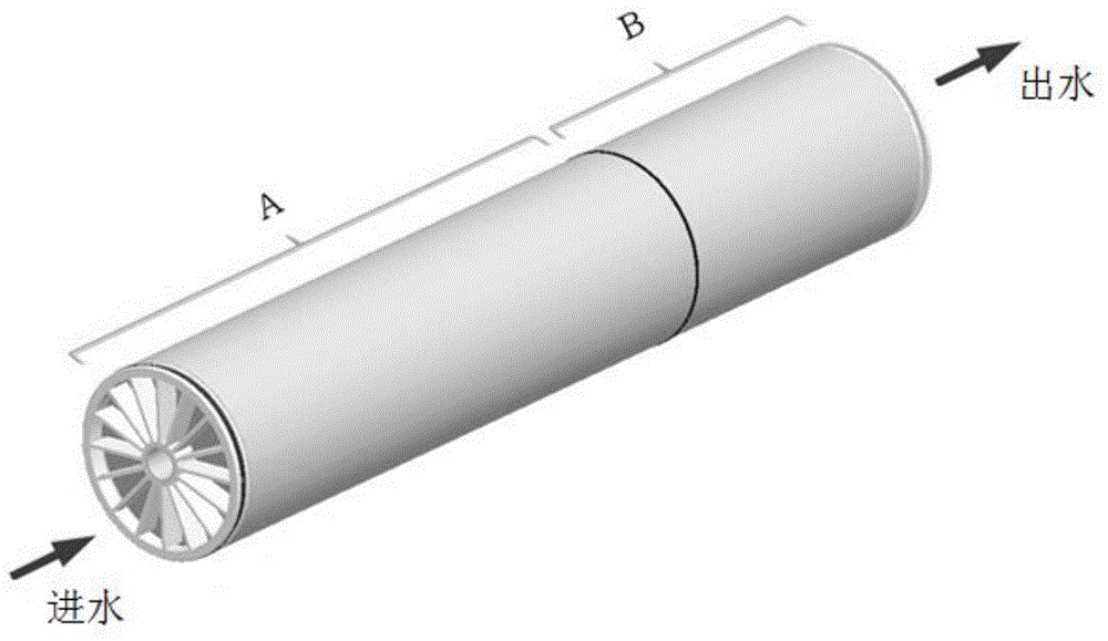
[0029] Such as figure 1 , 2 As shown in , 3, a roll-type membrane element includes a water inlet A and a water outlet B, wherein the water inlet A is connected to the high desalination membrane 1 through a connecting piece 7; the water outlet B is connected to the high flux membrane 2 Connected by connecting piece 7; and glue lines 6 are coated on the front and back sides of the high desalination membrane 1 and the high flux membrane 2; the high desalination membrane 1 and the high flux membrane 2 are used as membranes The innermost layer of the element, in turn outwards, also includes a thick net 3, a diaphragm 5, a thin net 4 and two layers of diaphragm 5 connected to the central axis of the membrane element composed of the water inlet A and the water outlet B through the connector 7 , wherein, the thick net 3, the diaphragm 5, the front and back of the first layer of diaphragm 5 behind the thin net 4 and the thin net 4 are all coated with glue lines 6, and the front side o...
Embodiment 2
[0042] On the basis of embodiment 1,
[0043] The diaphragm 5 behind the thick net 3 is 3 layers.
[0044] Described light net 4 is 4 layers.
[0045] The thickness of the thick net 3 is 30mil.
[0046] The membrane 5 is an ultrafiltration membrane.
Embodiment 3
[0048] On the basis of embodiment 1,
[0049] The diaphragm 5 behind the thick net 3 is 2 layers.
[0050] Described light net 4 is 3 layers.
[0051] The thickness of the thick net 3 is 29mil.
[0052] The membrane 5 is a reverse osmosis membrane.
[0053] In the rolling process of the rolled membrane element, the inner layer of high desalination membrane 1 and high flux membrane 2 can be wound around the central axis composed of water inlet A and water outlet B, and then Roll up the thick net 3, wrap the high desalination membrane 1 and the high flux membrane 2 and bond them together with the glue on the glue line 6, wrap the thick net 3 with the membrane 5 in turn, and then use the thin net 4 Wrapping the diaphragm 5, wrapping the light net 4 with the diaphragm 5, and adding a layer of diaphragm 5 for overall wrapping, the roll-type membrane element can be obtained.
[0054] When using the diaphragm 5, the diaphragm 5 between the thick net 3 and the thin net 4 is a comb...
PUM
 Abstract
Description
Claims
Application Information
 - R&D
- Intellectual Property
- Life Sciences
- Materials
- Tech Scout
- Unparalleled Data Quality
- Higher Quality Content
- 60% Fewer Hallucinations
Browse by: Latest US Patents, China's latest patents, Technical Efficacy Thesaurus, Application Domain, Technology Topic, Popular Technical Reports.
© 2025 PatSnap. All rights reserved.Legal|Privacy policy|Modern Slavery Act Transparency Statement|Sitemap|About US| Contact US: help@patsnap.com